Control Panel Troubleshooting
- Introduction
- My heating element isn't firing (or firing continuously)
- I think one of my elements died. Can I test it?
- A wire or part looks like it's burnt or melting!
- My temperatures are jumping around and / or one of my PIDs is displaying "orAL". What does that mean?
- My GFCI breaker trips as soon as I turn on the control panel
- My control panel doesn't turn on. It used to work fine.
- My 7A fuse keeps blowing
- One of my switches seems to work backwards
- My yellow ELEMENT ON lights glow dimly when heating elements are disconnected. Is that normal?
- I'm measuring voltage at the SSR output even though it's off. Is that normal?
- I'm measuring a short between the HOT and NEUTRAL buses. Is that normal?
- Can I test a PID without a temperature probe?


Introduction
Having issues with your Electric Brewery control panel? Our troubleshooting tips will help you get things resolved quickly!
These instructions apply to our Standard 30A Electric Brewery Control Panel for countries that support both 120V and 240V as documented in our build instructions and sold pre-assembled or in kit form. They are still useful for our alternate control panels but there will be slight (hopefully obvious) changes to some of these instructions depending on your panel version.
General precautions apply here as in some cases you may be required to take measurements inside a live panel to troubleshoot. Please be careful! If you are uncomfortable with this please refer to a qualified electrician.
Should you need them, replacement parts are available in our shop.
Take a look at our Testing Your Control Panel as You Build It guide too for additional hints/tips that may prove useful.
You may also contact us at sales@TheElectricBrewery.com. We support our products and customers for life.

Parts and tools


Purchasing through our affiliate links helps support our site at no extra cost to you. We thank you!
My heating element isn't firing (or firing continuously)

This is a common problem as it can occur due to numerous issues including incorrect wiring in the panel (if you wired your own panel), incorrect wall outlet wiring, incorrect power cord wiring, incorrect BOIL or HLT PID settings, incorrectly using the PID, a defective part or cable, or a combination of these. If you supplied your own parts instead of using one of our control panel kits then the problem may also be due to an incorrect or incompatible part.
Our heating elements will not wear out over time. They are not like light bulbs or other electronic devices that are consumed over time. Unless physically damaged, they will last a lifetime.
If your heating element isn't firing or is firing continuously, follow these steps to resolve the issue:
STEP 1: Ensure the panel is receiving 240 volts
If the panel volt meter is displaying approximately 240 volts it is correctly powered. Skip to STEP 2.
If the panel was recently moved and at the old location the panel volt meter correctly displayed approximately 240 volts, but displays only 0 to 120 volts volts at the new location, the wall outlet wiring at the new location is incorrect. Using a different power cord that is incorrectly wired may also cause this issue. It's possible to have the panel turn on but not have the heating element fire if the outlet and/or power cord is miswired.
First we'll ensure the standard 4 wire dryer outlet is correctly wired.
 A NEMA 14-30R 4 wire dryer outlet supplies both 120V and 240V AC with ground to our Standard 30A Electric Brewery Control Panel
Use your multimeter and refer to the diagram above. You should measure approximately 240V AC between the two HOT lines and approximately 120V AC between either of the HOT lines and NEUTRAL. If not, check your wall outlet / electrical panel breaker wiring. If you measure 0V AC between any of these test points, ensure that the circuit breaker in your electrical panel has not tripped. Reset if required. To reset any breaker turn it all the way OFF and then to the ON position.
If the wall outlet is correctly wired, next measure the voltage coming out of the 30A control panel power cord's L14-30 connector.
 L14-30 connector voltages and measuring points
You should once again measure approximately 240V AC between the two HOT lines and approximately 120V AC between either of the HOT lines and NEUTRAL. If not, check your power cord wiring.
Once you've fixed the wall outlet and/or power cord wiring the panel volt meter will display approximately 240 volts the heating element may fire correctly and problem solved! If not, continue with the next step.
STEP 2: Ensure temperature probe and heating element cords are connected
Make sure that the temperature probe and heating element cords are plugged into the corresponding control panel receptacles, and that the temperature is displayed on the PID's upper red PROCESS VALUE (PV). While there are ways to use a PID without a temperature probe, under normal use a temperature probe must be connected. If the PID is unable to communicate with the temperature probe an "orAL" error will be displayed on the PID's upper red PROCESS VALUE (PV) and this must be corrected before continuing.
STEP 3: Ensure PID settings are correct
PIDs are used in our control panels to tell the heating elements when to turn on and off. There are various settings that must be initially set. These only need to be set once. Even if these were originally set up, if things are not working correctly it's best to confirm that something wasn't changed inadvertently. See our Control Panel (Setup) guide for the correct PID settings.
STEP 4: Ensure the PID buttons are used correctly
PIDs can be set to work in AUTOMATIC mode, MANUAL mode, or both:
- AUTOMATIC mode (BOIL and HLT): The brewer sets the target temperature and the PID intelligently fires as required to heat up and hold at that temperature based on what the temperature probe sees. Automatic mode is used in the HLT to maintain specific temperatures and in the BOIL to do lower temperature hop stands (steeps).
- MANUAL mode (BOIL only): The brewer sets the power (0-100%) and the PID fires on and off continuously to maintain that level of power. Temperature is not used. The water or wort heats up to boiling and stays there. Manual mode is used in the BOIL to maintain the desired boil vigor based on batch size and brewer preference.
To use AUTOMATIC mode (temperature based), press the "A/M" button until the green "A-M" light is OFF. Press the UP/DOWN buttons until the lower green SET VALUE (SV) is at the desired temperature.
To use MANUAL mode (percentage power), press the "A/M" button until the green "A-M" light is ON. Press the UP/DOWN buttons until the lower green SET VALUE (SV) is at the desired power output (0-100%).
Note: A PID can be displaying AUTOMATIC or MANUAL mode numbers regardless of what mode it's actually running in. This can cause confusion. Press the SET button to switch display modes if what you see in the lower green SET VALUE (SV) number doesn't match what the "A-M" light shows. 99% of the time if the panel was known to be working before but someone new to using it is having troubles, simply pressing this button will get things working.
Detailed steps for firing kettle elements:
Firing the HLT element: If the HLT PID settings are correct it will only work in AUTOMATIC mode. Manual mode will not be available, and pressing the "A/M" button on the HLT PID to switch between modes will do nothing. Press the UP/DOWN buttons on the HLT PID until the lower green SET VALUE (SV) is at the desired temperature. If this SV value is higher than the upper red PROCESS VALUE (PV), the green PID "OUT" light will turn ON. Turn the ELEMENT SELECT switch to HLT and the HLT element will fire continuously. As the HLT heats up the measured red PROCESS VALUE (PV) temperature will rise up to and hold at the green SET VALUE (SV) temperature.
Firing the BOIL element: If the BOIL PID settings are correct it will work in both AUTOMATIC and MANUAL modes. To switch to MANUAL mode press the "A/M" button until the "A-M" light is ON. You should see the lower green SET VALUE (SV) number display as "M XXX" where XXX is a number from 0 to 100. If the "M" is not displayed press the SET button to switch the display mode. Press the UP / DOWN buttons on the BOIL PID until the lower green SV number reads "M 100". Turn the ELEMENT SELECT switch to BOIL and the BOIL element will fire 100% of the time. Turn down as desired. If you wish to run the BOIL in AUTOMATIC mode, press the "A/M" button to switch and then press the UP / DOWN buttons to set the temperature.
For in-depth instructions on using the control panel see our Brew Day Step by Step guide.
If the above instructions do not cause the heating element to fire and you've verified that the PID settings are correct, there's likely a wiring error or a defective part that needs replacing. Double check your wiring. If a part is defective it's quick and simple to do. We cover this in the remainder of the instructions below.
Keep in mind that all our panels are redundant: The BOIL and HLT sides are mirror images of each other. If a part on either of the sides has failed, simply swap the heating element and temperature probe cords to the other side and continue on with your brew day. You may then assess and replace the defective part later during downtime.
STEP 5: Assess which part is defective
If you still do not have power to a heating element after following the instructions above (or a heating element is always on) and you've confirmed that wiring is correct (assuming you wired your own), it's most likely that a part is defective. Use the information below to troubleshoot.
Control from the BOIL or HLT PID to the corresponding heating element goes through parts like this:
PID -> SSR -> ELEMENT SELECT switch -> RELAY -> ELEMENT and yellow ELEMENT ON light
(Click on the above links to see what the parts look like)
When the BOIL or HLT PID is sending a signal to turn on the element, the green PID "OUT" light should be ON. If it isn't on and you expect it to be, stop there and look at the PID for the problem. The settings may be incorrect, the temperature may be set too low, or you may be using the PID incorrectly. See the previous instructions above.
If the green PID "OUT" light is on then the SSR should be receiving a signal and turning on too. The PID "OUT" light and the SSR light (assuming your SSR has a light) should always be on at the same time. If the SSR light isn't on then either the PID is defective, the wiring between the PID and the SSR is incorrect (check your wiring), or the SSR is defective. To troubleshoot a possibly defective PID or SSR, swap wires with another known working PID or SSR.

If the SSR light is on but there's no heat at the element, then either the relay between the SSR and the element isn't closed, there's a problem with the element, the wiring somewhere from the SSR -> ELEMENT SELECT SWITCH -> RELAY -> ELEMENT is incorrect, the relay is defective, you have not turned the ELEMENT SELECT switch to one of the two ON positions, or the wrong contactors have been used in the ELEMENT SELECT switch. If using one of our 50A control panels check the corresponding fuses or breakers too. It is also possible that the element itself is defective. Switching the ELEMENT SELECT switch to either ON position should make the corresponding RELAY close with an audible 'clunk' - if it doesn't check your ELEMENT SELECT switch wiring. It could also be that the wall outlet supplying 120V AC and 240V AC to the panel is wired incorrectly such that only 120V AC is available and not 240V AC.
If the ELEMENT SELECT switch is turned to either of the ON positions to power the BOIL or the HLT, the corresponding yellow ELEMENT ON light on the front of the control panel should be turning on and off in unison with the corresponding PID "OUT" light and the SSR light. All three should be turning on and off at the same time. If the SSR light is ON when the PID "OUT" light is OFF, then the SSR is likely incorrectly receiving a signal to turn on all the time. Check your PID and SSR wiring. The SSR may also be defective. If the ELEMENT ON light is ON when the PID "OUT" light and SSR light are OFF then the element receptacle is receiving 240V AC when it shouldn't. Check your relay and SSR wiring. The relay and SSR may also both be defective, but a double failure is highly improbable.
If everything in the control panel appears to be working correctly to this point, use a multimeter to (carefully) measure the two HOT connection points on the heating element receptacle on the bottom of the control panel - careful not to short the probes together! With the ELEMENT SELECT SWITCH in either ON position to close the corresponding relay and the PID firing a signal to turn on the SSR, you should be measuring 240V AC. If you do measure 240V AC, the control panel is working correctly and the problem is external to the control panel and will be somewhere in the heating element cord, plug, or box. If using one of our 50A control panels you may also check the corresponding breakers or fuses for continuity using a multimeter.
If one of the yellow ELEMENT ON lights does not light up but the corresponding heating element is firing, then the ELEMENT ON light is either wired incorrectly or is defective. The LED nature of these lights means that they should last a very long time but failures do happen with any equipment. The ELEMENT ON lights do not need to function for the heating elements to fire.
Using a multimeter to measure for 240V AC at the various points along the chain can help troubleshoot the issue further.
Replacement parts are available in our shop.

I think one of my elements died. Can I test it?
Our heating elements will not wear out over time. They are not like light bulbs or other electronic devices that are consumed over time. Unless physically damaged, they will last a lifetime.
If you believe you damaged a heating element, you can test it as follows:
Unplug your heating element from the control panel and remove the cover from your heating element box using a screwdriver.
Measure the resistance across the element by measuring between the two screw connection points using a multimeter.
Resistance on our 5500W elements is approximately 10.4 ohms, while resistance on our 4500W elements is approximately 12.8 ohms. Make sure your multimeter was properly zeroed first to negate any resistance from the probe wires. If the heating element is defective you will most likely measure an open circuit (infinite resistance). This can happen if the heating element is accidentally damaged or fired dry (not submerged in water or wort) for more than a few seconds.
If the measured resistance is correct and you're running one of our 50A Electric Brewery Control Panels, check your control panel fuses or breakers.
Replacement heating elements are available in our shop.
A wire or part looks like it's burnt or melting!
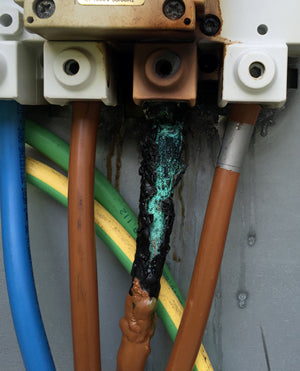
This is most likely to happen when building your own control panel and wiring connections are not done properly, causing excessive heat. This heat is created when current flows through an area that is too small to handle the amount of current. This can happen for one or more of the following reasons:
- When connections are not properly fastened / tightened / crimped such that only a few strands are making contact. Make sure to fasten securely.
- When an undersized wire or part is used that cannot handle the current. Always use the recommended wire gauge (or larger). The thicker the wire, the more current it can handle. Always use wire that is rated to the voltage being passed (or higher). Always use parts rated to at least the voltage and current that will be used. This includes crimp on spades, terminals, and ferrules (where appropriate).
- When some of the wire copper strands are cut / trimmed to get it to fit. This should never be done as it reduces the wire gauge, effectively re-creating item (2) above.
- When an electrical socket or plug blade is dirty or charred, or the plug is not pushed and locked in properly with the receptacle. Avoid getting plug blades wet or dirty, clean them if they are no longer shiny.
All of these cases effectively reduce the contact area meaning that more current flows through a smaller area which in turn creates excess heat. Often this heat will damage surrounding components as well. Look first to where the heat is created. If a wire is discoloured or melting, it's likely the closest spot to the bad connection.
It could also be that you're actually pulling too much current by using oversized heating elements (larger than 5500W). This would only be possible if an incorrectly sized breaker was installed in the electrical panel (larger than 30 or 50 amps, depending on your control panel model) as otherwise the breaker would trip. A double pole 30A or 50A GFCI breaker should be used (sized for your control panel) per our control panel build instructions or order pages.
When done correctly an electrical connection will never need re-tightening under normal use. If a connection is found to be loose, the proper method is to cut used strands of wire off, strip insulation off, and terminate again.
Note that cheaper parts tend to be more easily damaged. This is especially true for soft rubber molded plugs that are used by some to lower cost. These rubber molded plugs melt or become deformed much easier than the industrial grade nylon plugs / connectors / receptacles we sell and use on all of our equipment.
Any parts or wiring that are damaged or discoloured from heat should be replaced. Replacement parts are available in our shop.
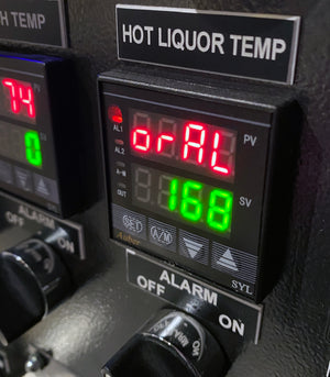
My temperatures are jumping around and / or one of my PIDs is displaying "orAL". What does that mean?
Our temperature probe and cables will not wear out over time. They are not like light bulbs or other electronic devices that are consumed over time. Unless physically damaged, they will last a lifetime.
If a PID is flashing "orAL" (short for 'over range ALarm') then the PID is unable to communicate with the temperature probe. This can happen if the temperature probe is not connected (wired) correctly to the PID, the temperature probe type in the PID is set incorrectly, the temperature probe is defective, the temperature probe cable is defective, the PID is defective, or a combination of the above.
Before a PID flashes the "orAL" error after losing connectivity with the probe the PV temperature value displayed on the PID will increase or decrease very quickly at a rate of approximately 100 degrees per second. The probe is connected to the PID using 3 wires connected to screws 3, 4, and 5 on the PID. If the wire to screw 3 is disconnected the PV temperature will drop very quickly. If the wire to either screw 4 or 5 is disconnected the PV temperature will rise very quickly. Once the PV temperature exceeds the allowable range the PID will flash "orAL". If a disconnected wire is reconnected, the PV temperature will slowly return to normal and the "orAL" error will no longer be shown.
Sometimes when the PID to temperature probe connectivity is intermittent or there is a bad/loose connection between the two, the PV temperature value displayed will appear to jump around.
To set the temperature probe type correctly refer to your PID manual, or if using one of our control panels refer to our Control Panel (Setup) instructions.
The most common reason for the error on systems that worked previously is physical damage to the temperature probe and / or cable as these items are exposed. You can test by swapping with a known working temperature probe and cable. Sometimes the connection point between the two is damaged so it's usually best to swap both the probe and cable. If you've confirmed by swapping both that the issue is with the probe and / or cable, try swapping just one of the two to see if the problem can isolated to one or the other. If after you swapped the probe and cable the problem stayed with the PID, we know the issue is with the PID and / or wiring from the PID to the control panel XLR receptacle. Swapping wiring inside the panel between XLR receptacles and PIDs can help isolate the issue.
The connection point between the temperature probe tip and cable can be damaged if one is not careful when disconnecting / reconnecting the cable and the connectors are twisted and / or turned when connecting instead of lining up the tabs and pushing them together straight. There's a little tab that needs to be lined up when you mate the two halves together. To connect / disconnect, the tabs need to be lined up and pushed together. They should NEVER BE TWISTED / TURNED as you may damage one or both ends. Twisting / turning can pull apart the wires inside the connector.
If twisting / turning caused damage and you are handy with a soldering iron, you can easily repair the probe yourself. Remove the four small screws from the back of the probe and slide the resistor and cable end out of the probe (you should not have to remove it from the kettle or tee). You will see one end of the resistor soldered to pin #2, and the other side soldered to either pin #1 or #3 with a jumper between the two. One of those points is most likely broken and / or making intermittent contact. A quick re-soldering is all that is needed. To get into the connector on the cable, plug the cable end into one of the probes to prevent it from spinning and rotate the winged portion counter clockwise and it will unscrew from the other section allowing you access to the connections. We recommend desoldering all 3 wires (if not already detached), trimming them back a little, and making sure there is a good solder connection.
Replacement parts, cables, probe tips, and PIDs are available in our shop.
My GFCI breaker trips as soon as I turn on the control panel
If your electrical panel GFCI breaker trips as soon as you turn on the control panel, the GFCI breaker may be wired incorrectly. This is especially true if using a control panel that has been pre-assembled by us as they are all tested under load prior to shipping. Also true if the panel worked in one location but now trips a GFCI breaker at a different location.
Miswiring a GFCI breaker is unfortunately very common, even by licenced electricians. Check that the GFCI breaker NEUTRAL wire (white) coming from the wall outlet is connected to the breaker NEUTRAL pole and that the white pigtail wire from the GFCI breaker is connected to the NEUTRAL bus bar in the electrical panel. Most often when wired incorrectly the NEUTRAL wire (white) coming from the wall outlet is incorrectly connected to the NEUTRAL bus bar in the electrical panel through the pigtail (this is how non-GFCI breakers are wired).
More information is available in STEP 1: Supply power from our control panel build instructions.
If you are sure the GFCI breaker is wired correctly and you are testing a control panel for the first time that you wired yourself, you have likely miswired something. Check your control panel and power cord wiring. If you supplied your own parts instead of using one of our control panel kits then the problem may also be due to an incorrect or incompatible part.
My control panel doesn't turn on. It used to work fine.
If you built your control panel following our design (or purchased one pre-assembled) it will include a safe start interlock feature that does not allow the panel to turn if any of the pumps or heating element switches are in the ON position. If your panel worked fine before but now refuses to turn on, make sure both PUMP switches and the ELEMENT SELECT switch are in the OFF position before you try turning on the panel. The panel will not turn on if any of these switches are in the ON position.
If you've confirmed that these switches are off and the panel still won't turn on, we'll need to use a multimeter to measure the voltages being fed into and throughout the panel systematically to find the issue, starting at the wall outlet.
If the panel and panel power cord were moved and they work correctly at the old location but the panel does not turn on at the new location (or displays 0 volts or very low volts instead of approximately 240 volts), the issue is incorrect wall outlet wiring at the new location.
First we'll ensure the standard 4 wire dryer outlet is correctly wired.
A NEMA 14-30R 4 wire dryer outlet supplies both 120V and 240V AC with ground to our Standard 30A Electric Brewery Control Panel
Use your multimeter and refer to the diagram above. You should measure approximately 240V AC between the two HOT lines and approximately 120V AC between either of the HOT lines and NEUTRAL. If not, check your wall outlet / electrical panel breaker wiring. If you measure 0V AC between any of these test points, ensure that the circuit breaker in your electrical panel has not tripped. Reset if required. To reset any breaker turn it all the way OFF and then to the ON position.
If the wall outlet is correctly wired, next measure the voltage coming out of the 30A control panel power cord's L14-30 connector.
L14-30 connector voltages and measuring points
You should once again measure approximately 240V AC between the two HOT lines and approximately 120V AC between either of the HOT lines and NEUTRAL. If not, check your power cord wiring.
If you've confirmed that the power cord is feeding power to the control panel correctly, check the 7A fuse inside the panel to ensure it has not blown. If it has blown, this means either a pump or a 120V AC part in the panel has shorted and the 7A fuse is simply doing its job to protect wiring and other components. The defective pump or part (PIDs, timer, buzzer, transformers, DC power supplies, relays, all lights except ELEMENT ON) will need to be fixed or replaced before the fuse is replaced. Parts may be disconnected one at time to confirm. Replacements are available in our shop.
If the 7A fuse is blown it may also be that you are using an overrated current device in one of your control panel pump receptacles that increases current draw higher than the maximum 7 amps. This should not be done. The 7A fuse size is chosen to ensure that the draw from the pumps combined with the heating element(s) does not exceed the electrical panel breaker limit.
If you've confirmed that the 7A fuse is not blown, it is most likely that one of the following parts responsible for the safe start interlock feature is defective and not allowing current to pass for the panel to the turn on:
- POWER KEY switch NO contactor
- ELEMENT SELECT switch NC contactors
- WATER PUMP switch NC contactor
- WORT PUMP switch NC contactor
- SAFE START INTERLOCK relay
- POWER IN relay
These parts are shown in the following wiring diagram:
 Standard 30A Electric Brewery Control Panel safe start interlock wiring diagram
To test these parts, follow these steps:
- Turn all of the switches to the OFF position.
- Turn the POWER KEY switch to the ON position.
- Using a multimeter, measure the voltage between NEUTRAL (such as from the NEUTRAL bus) and the various points along the wiring diagram above starting at the POWER IN receptacle to ensure that you see 120V AC. Start by measuring between NEUTRAL and point "Y" on the POWER IN receptacle. You should measure 120V AC. If you do not, go back and check your power cord and wall outlet / electrical panel breaker wiring.
- Next measure between NEUTRAL and the side of the POWER KEY switch NO contactor that is not directly wired to the POWER IN receptacle (this is the output side). With the POWER key switch in the ON position you should measure 120V AC. If you see 0V AC the POWER KEY switch NO contactor is defective and should be replaced. Replacements are available in our shop.
- Continue working along the diagram measuring between NEUTRAL and the various switch NC contactors one at a time (ELEMENT SELECT switch, WATER PUMP switch, and WORT PUMP switch), always measuring the contactor side electrically farthest from the POWER IN receptacle (the output side). If you measure 120V AC between NEUTRAL and the NC switch contactor for all switches then the switch NC contactors are fine and 120V AC is making it to the SAFE START INTERLOCK relay. If you see 0V AC at any contactor output, the contactor is defective and should be replaced. Replacements are available in our shop.
- Measure between NEUTRAL and screw 2 on the SAFE START INTERLOCK relay. You should measure 120V AC. Next measure between NEUTRAL and the SAFE START INTERLOCK relay screw 3. You should measure 120V AC. If not, the SAFE START INTERLOCK relay is not closing (you will not see it close when you turn on the POWER KEY switch) and should be replaced. Replacements are available in our shop.
- If the SAFE START INTERLOCK relay screw 3 measures 120V AC then 120V AC is making it to the POWER IN relay. The POWER IN relay is most likely defective and not closing properly. With the POWER IN switch ON and all other switches OFF, you should measure 120V AC between NEUTRAL and the left (input) side of POWER IN relay coil and 0V AC between NEUTRAL and the right (output) side of the POWER IN relay coil. If this is true and the relay does not open / close as you turn the POWER IN switch ON / OFF, the POWER in relay is defective. Replacements are available in our shop.
My 7A fuse keeps blowing
If the 7A fuse blows continuously then either a pump or a 120V AC part in the panel has shorted and the 7A fuse is simply doing its job to protect wiring and other components. The defective pump or part (PIDs, timer, buzzer, transformers, DC power supplies, relays, all lights except ELEMENT ON) will need to be fixed or replaced before the fuse is replaced. Parts may be disconnected one at time to confirm. Replacements are available in our shop.
It may also be that you are using an overrated current device in one of your control panel pump receptacles that increases current draw higher than the maximum 7 amps. This should not be done. The 7A fuse size is chosen to ensure that the draw from the pumps combined with the heating element(s) does not exceed the electrical panel breaker limit.

One of my switches seems to work backwards
Switches use either normally open (NO) or normally closed (NC) contactors (or both). The ones we sell and include in our control panels (both kits and pre-assembled) are colour coded green (NO) and red (NC) for easy identification. When wiring your own panel, make sure to use the correct ones following our wiring guides.
If you are sure the correct contactors are being used, reverse the position on the switch. For example, if the switch has the correct contactor installed on the left side and the switch is working backwards, install the contactor on the right.
Ignore the 1/2/3/4 numbers marking the connection points on some contactors. Contactors are not polarized (there are no specific in or out connection points) so it doesn't matter which side of the contactor is used for input or output when wiring.
My yellow ELEMENT ON lights glow dimly when heating elements are disconnected. Is that normal?
Yes. This is normal. Turning the ELEMENT SELECT switch to either ON position without the heating element connected to the control panel will cause the corresponding yellow ELEMENT ON light to glow dimly even when the PID is not telling the SSR to turn on. It will not occur when a heating element is connected.
All SSRs have a small amount of leakage current and without the element connected to sink that current, the LED light will glow dimly.
I'm measuring voltage at the SSR output even though it's off. Is that normal?
Yes. This is normal. Since SSRs have voltage / current characteristics of semiconductors rather than mechanical relays, they have a small amount of leakage current which causes voltage to be measured on the output at all times. This is inherent to all SSRs. You cannot use regular continuity (resistance) or voltage testing to test an SSR.
Since very little current is allowed to flow when the SSR is off, the heating element will not fire even though voltage is present at all times on the SSR output. This leakage current is one of the reasons why our control panel design includes the added safety of mechanical relays to physically disconnect the power from the heating elements (controlled by the ELEMENT SELECT switch). The mechanical relays ensure that there is a complete physical disconnect between both HOT lines and the heating elements when the relays are off. This is important as when SSRs fail they tend to fail closed (on) and brewers are often working in or cleaning one kettle while the other is operational.
I'm measuring a short between the HOT and NEUTRAL buses. Is that normal?
Yes. This is normal, and is due to the doorbell transformers connected to the HOT and NEUTRAL buses.
Inside the doorbell transformers are two (or more) coils of wire wrapped around a core (usually iron). If you measure between the buses with a multimeter to test continuity, you'll measure a short due to these transformer coils. Through the laws of electromagnetic induction, when you turn the control panel on and 120V AC is fed into the transformers you do not draw infinite current and pop a fuse / breaker.
Can I test a PID without a temperature probe?
Our PIDs require that a temperature probe be connected in order for them to work, even if you want to run them in manual mode (such as it done in the boil kettle).
If you wish to test one of our PIDs without a temperature probe, set the PID SN setting to 0 to set the probe type to a 2-wire thermocouple probe and then use a copper wire to short the PID terminals 4 & 5 together. The PID will then display ambient temperature and you'll be able to run the PID in manual mode.

