50A Electric Brewery Control Panel for 30+ gallons
This control panel is available in pre-built or kit form through our shop.
These wiring instructions are for our 50A Electric Brewery Control Panel for 30+ gallons for countries where the mains power has both 110-120V and 220-240V available such the United States, Canada, Mexico, most of the Caribbean / Central America / South America, Japan, and Taiwan.
Up to two elements are used per kettle (instead of one) with one kettle powered at a time. If you're consistently producing 30 gallons or more, or think you may want to in the future, this is the panel for you. You may use a single heating element per kettle for now and add more in the future. Also useful for those who want faster ramp/heating times with any batch size. Perfect for 1-3 bbl pilot systems.
Need more power or something custom? Our panels can be interlocked with optional modular booster panels to increase capacity as you grow. Contact us for details.


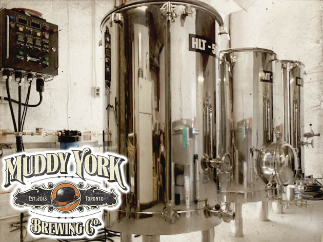
Muddy York Brewing Co. using our 50A control panel for 30+ gallons on their 3.5 bbl setup. (More pictures) 
Lochiel Brewing using our 50A control panel for 30+ gallons on their 1 bbl brewhouse. (More pictures) 
FAQ
When would I want a 50A control panel for 30+ gallons?
Our standard 30A control panel is adequate for brewers looking to produce up to around 20 gallons of finished product. A single 5500W element is used in both the boil kettle and hot liquor tank.
To produce 30 gallons or more, some brewers prefer to have more power for faster heating (ramp) times and to ensure a vigorous boil regardless of ambient temperature. With the 50A control panel for 30+ gallons the single 5500W elements are replaced with two 4500-5500W elements for a total of 9000-11000W per kettle. Consider this control panel for if you're interested in producing more than 20 gallons of finished product and wish to speed up your brew day by reducing heat times. If you're consistently producing 30 gallons or more then we highly recommend this control panel be used.
Only brewing smaller (5-20 gallon) batches now but may want to go bigger in the future? Consider this 50A control panel for 30+ gallons. It will let you use one element per kettle now, and and add a second in the future for more power. If you're looking for the fastest heating/ramp times possible on even smaller batches, consider using this control panel and adding two heating elements in the hot liquor tank.
Need more power or something custom? Our panels can be interlocked with optional modular booster panels to increase capacity as you grow. Contact us for details.
Are there any downsides to using this control panel?
Cost is the only downside. 50A components and wiring are more expensive than similar 30A rated items. Unless you want to consistently brew over 20 gallons at once or wish to upgrade in the future, we recommend sticking with the original 30 amp control panel design. Many brewers producing 20 gallons per batch are happily using 5500W per kettle with the standard 30A control panel. Some 1 bbl (31 gallon) brewers are also successfully using the standard 30A control panel. Others who only occasionally want to brew larger batches will brew two separate batches and combine them. The choice is yours.
Can I use this control panel to brew less than 20 gallons?
Yes. More power simply means faster heating. Some brewers will use a 50A control panel to be future proof. It gives them the capability to add more power with a larger future setup without having to replace or modify the control panel. If one of the heating elements will not be submersed when brewing smaller batches, that heating element should be unplugged from the control panel. The control panel will still operate normally.
Can I unplug one of the heating elements when making smaller batches?
Yes. See above.
How much faster does 9000-11000W heat compared to 5500W?
A 5500W heating element such as the one we use with our standard 30A control panel will raise the temperature of 1 gallon of water by 1 degree Fahrenheit in approximately 1.6 seconds. 9000W reduces this time to 1.0 seconds. 11000W reduces this time to 0.8 seconds.
Some real world examples:
- Heat 30 gallons of strike water from 70F to 155F: 68 minutes with 5500W, 42 minutes with 9000W, 34 minutes with 11000W
- Bring 24 gallons of wort from 150F to boil: 40 minutes with 5500W, 24 minutes with 9000W, 20 minutes with 11000W
What changes are needed to upgrade from 30A to 50A?
All of the 30A devices (and wiring) in the control panel are upgraded to 50A and we add one extra element to both the Boil Kettle and hot liquor tank. The 30A standard dryer outlet is replaced with a 50A stove outlet. See below for complete details on the changes required.
Are instructions available for countries that run only at 220-240V?
Yes. See 50A Electric Brewery Control Panel for 30+ gallons (240V only, for international use). Kits with parts are available too in our shop.
Do I still need to use a ground fault circuit interrupter (GFCI)?
Yes. A GFCI is required for safety reasons. In most cases this will be done with a 50A/240V 2-pole GFCI breaker in the electrical breaker panel. For more information on GFCIs see STEP 1: Supply power of our Control Panel build instructions.
Do I need a larger enclosure?
Two extra element receptacles are required on the bottom of the enclosure. There is room on the standard 16x16x8" enclosure we use if you're careful about placement (see above for pictures). Consider using a larger 20x20x8" enclosure for more room to work in. Keep in mind that the control layout may have the be re-thought if a larger enclosure is used and the handles may not be long enough. Our pre-built control panels and kits all use the same 16x16x8" enclosure.
Can a buy a control panel kit that includes all the parts I need already included?
Yes. We can supply control panel kits for any country including those where only 240V is available (outside North America). We can even pre-punch the enclosure for you to save work. See our shop.
Can I buy this control panel completely assembled and tested?
Yes. Like our standard 30A panel the enclosure is professional cut and painted to our specifications and then wired, and tested. See our shop.
WIRING/PART CHANGES
Follow the wiring diagrams below.
If you're new to wiring we recommend you read our instructions for our standard 30A control panel build as we present some general wiring concepts, hints, and tips.
POWER CORD / SUPPLY POWER
A 50A 4-conductor stove power cord attached to a Locking Grounded California-Style connector (125/250VAC, 50A) is used as the power cord: 


The stove cord has 4 conductors (2 HOTS, 1 NEUTRAL, and GROUND) and a NEMA 14-50R plug on the end. Conductors must be at least 6 ga for the two HOT lines and at least 8 ga for NEUTRAL and GROUND. You will need to install a 240V/50A circuit in the house terminated with a NEMA 14-50R receptacle on the wall to power the control panel. The power cord plugs into this receptacle which looks like this: 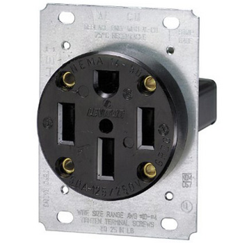
This circuit should be wired to a 50 amp 2-pole GFCI breaker in the electrical breaker panel using the correct size wire between the two (6 ga wire by most electrical codes). The breaker must be 50 amps and not larger in order to protect the 6 ga wiring in the control panel.
Note that stoves typically come in 40 and 50 amp varieties with 40 amp being the more common of the two. In most houses stove circuits will only be 40 amps (typically a 40 amp breaker in the panel and 8 ga wire) since home builders do whatever is cheapest. 40A is not enough. The circuit must be able to deliver 50 amps for this 50 amp control panel. The actual receptacle you plug the stove into is usually rated 50 amps even for 40 amp circuits (since the plug is the same) but the wiring in the wall and the breaker in the panel itself will only be rated to 40 amps. If you're wiring up a new stove outlet make sure to tell your electrician that you require a 50 amp circuit, not 40 amp.
POWER INPUT
The power in receptacle and relay are changed to handle the larger 50A (resistive) load. 50A relays are difficult to find so a contactor is used instead. A relay and contactor (the terms are often used interchangeably) work the same way but contactors are generally rated for higher power. Note that a contactor rated for 40A inductive load (as presented by compressors in air conditioners or similar) is able to drive a 50A resistive load as presented by our heating elements. So if you find a 40A "inductive" contactor it's likely ok to use at 50A "resistive". Confirm that the model you intend on ordering can support 50A "resistive". Some of the 10 gauge wire is replaced with 6 gauge to handle the 50A load. Any ring terminals or connectors (if used) for connecting the 6 ga wire must also be rated for at least 50 amps.
Part changes as compared to our standard 30A control panel build:
(Qty: 1) 2 pole 50A (resistive) 240VAC contactor with 110-120VAC coil
(Qty: 1) Locking Grounded California-Style male receptacle (125/250VAC, 50A)
(~1 foot) Black 6 gauge type T90/THWN/THHN wire
Wiring diagram (changes as compared to our standard 30A control panel build are shown in yellow): 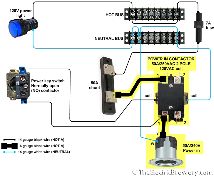
GROUND
Two extra ground wires are required for the two new element receptacles. The ground wire from the power input receptacle is increased from 10 to 6 gauge. There may not be enough room on the enclosure ground post for all these ground wires so you may want to use a 10 terminal 50A ground bar on the back plate instead. Make sure to connect the door and enclosure ground posts to the ground bar as well. Any ring terminals or connectors (if used) for connecting the 6 ga wire must also be rated for at least 50 amps.
Part changes as compared to our standard 30A control panel build:
(Qty: 1) 7-10 terminal 50A ground bar (optional)
(4 feet) Green 10 gauge type T90/THWN/THHN wire
(~2 feet) Green 6 gauge type T90/THWN/THHN wire
Wiring diagram (changes as compared to our standard 30A control panel build are shown in yellow): 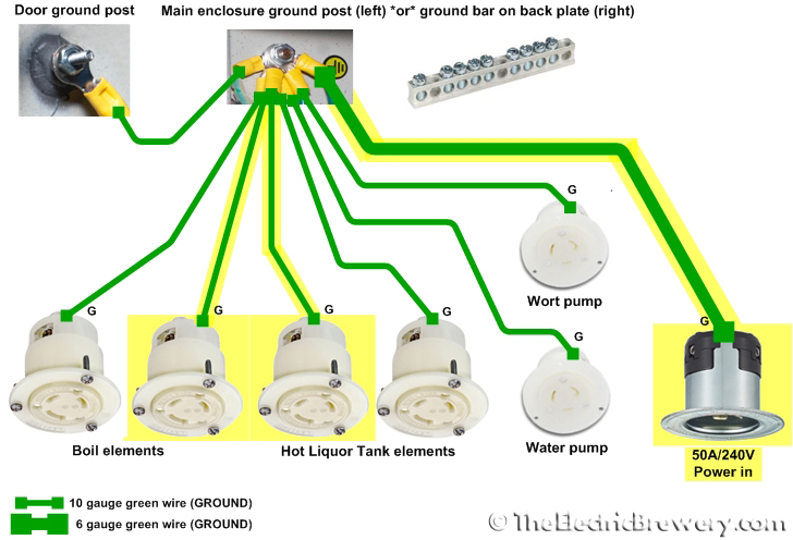
VOLT AND AMP METERS
The boil relay is changed to a contactor to handle the larger 50A (resistive) load. 50A relays are difficult to find so a contactor is used instead.
Part changes as compared to our standard 30A control panel build:
(Qty: 1) 2 pole 50A (resistive) 240VAC contactor with 110-120VAC coil
As per the standard 30A control panel build wiring instructions, make sure to adjust the DC power supplies to +5VDC or slightly below before connecting to the meters as otherwise the meters may be damaged.
Wiring diagram (changes as compared to our standard 30A control panel build are shown in yellow): 
PUMPS
There are no changes to the pump wiring. 
PID CONTROLLERS
The SSRs are upgrade from 40A to 80A to handle the increased load of using up to 11000W. The custom heatsink we designed is more than large enough.
Part changes as compared to our standard 30A control panel build:
(Qty: 2) 80 amp SSR (12VDC input voltage, 240VAC output voltage)
Wiring diagram (changes as compared to our standard 30A control panel build are shown in yellow): 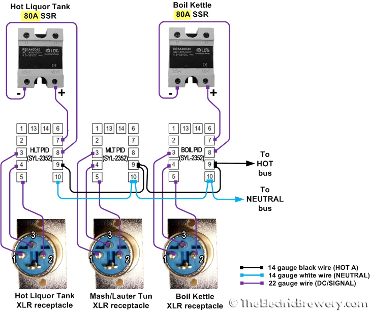
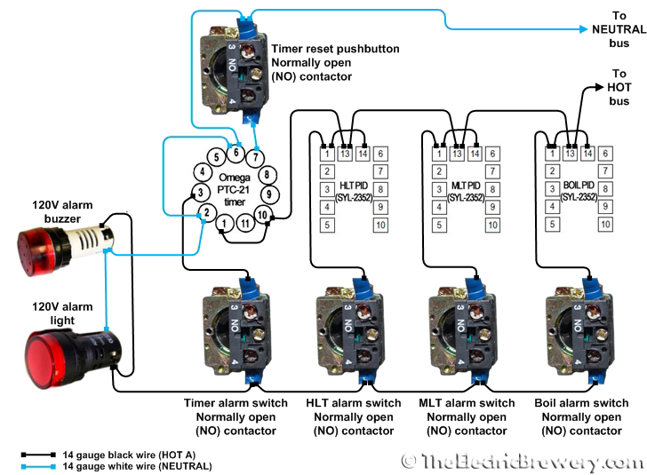
TIMER AND ALARMS
There are no changes to the timer and alarm wiring:
Timer and alarm wiring diagram if using the newer JSL-74A timer:

Timer and alarm wiring diagram if using the original Eagle B506-5001/Omega PTC-21 timer:
HEATING ELEMENTS
The last 30A relay is changed to a 50A (resistive) contactor. Two extra element receptacles are added and wired in parallel (not series) to the existing elements. Some of the 10 gauge wire is replaced with 6 gauge to handle the 50A load. 30A fuses are added to protect the 30A element receptacles and wiring. Why? On the standard 30A control panel the 30A circuit breaker in the electrical panel wall protects the 10 ga wiring so additional fuses are not required. With this 50A panel the 50A circuit breaker in the electrical panel protects the 6ga wiring but we now need to add protection for the smaller 10ga wiring between the contactors and the kettles (both inside the panel and out). Any ring terminals or connectors (if used) for connecting the 6 ga wire must also be rated for at least 50 amps.
Part changes as compared to our standard 30A control panel build:
(Qty: 1) 2 pole 50A (resistive) 240VAC contactor with 110-120VAC coil
(Qty: 2) NEMA L6-30 (250VAC, 30A) twist lock electrical female receptacle
(~7 feet) Black 6 gauge type T90/THWN/THHN wire
(~4 feet) Red 6 gauge type T90/THWN/THHN wire
(~2 feet) Black 10 gauge type T90/THWN/THHN wire
(~2 feet) Red 10 gauge type T90/THWN/THHN wire
(Qty: 8) 30A 250V fast blow fiber fuse
(Qty: 4) 30A 250V 2-pole fuse holder
Wiring diagram (changes as compared to our standard 30A control panel build are shown in yellow): 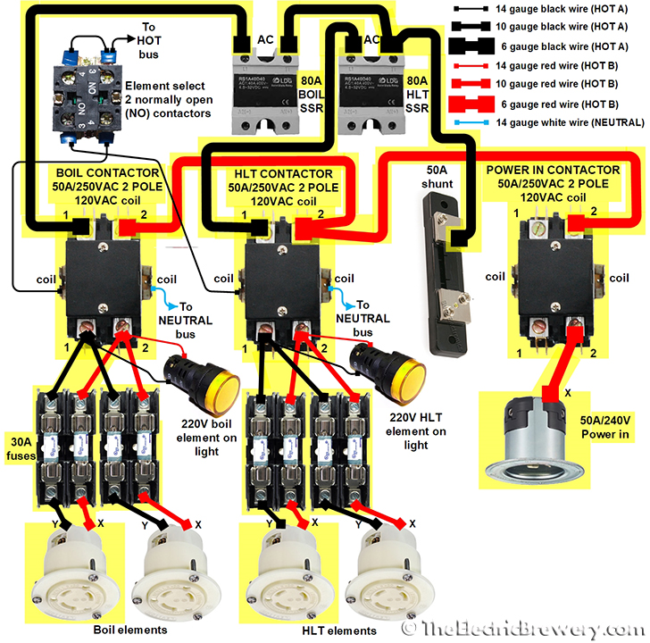
Note: With some contactor brands you may find it difficult to fit the two large 6 gauge red wires in the same screw hole at the top input #2 on the HLT contactor. Do not under any circumstances trim back strands of the wire to make them fit! Instead, use a power distribution block. Our control panel kits include this extra part (when required). Simply attach the 6 ga wire from the POWER IN CONTACTOR into the big end of distribution block and then two 6 ga wires out the other end that lead to the BOIL and HLT contactors.
SAFE START INTERLOCK
The power in receptacle and relay were changed to handle the larger 50A load as described previously. No further changes are required.
The POWER KEY switch was previously wired directly to the POWER IN CONTACTOR coil (per the POWER INPUT wiring diagram above). This wire must be removed otherwise the interlock feature will be bypassed and the control panel will power up regardless of how the three other switches are set.
Previously the WORT PUMP and WATER PUMP switches only had their normally open (NO) contactor wired up (per the PUMPS wiring diagram above). We are now adding a normally closed (NC) contactor beside the existing contactor. Only the new wiring is shown here. The existing wiring does not change.
Previously the ELEMENT SELECT switch contained two normally open (NO) contactor that were wired up (per the HEATING ELEMENTS wiring diagram above). We are now adding two normally closed (NC) contactors on top of the existing contactors. Only the new wiring is shown here. The existing wiring does not change.
As per the standard safe start interlock instructions for the 30A panel, the two normally closed (NC) contactors that are added to the Element Select switch are screwed on top of the existing normally open (NO) contactors as shown in the picture below. Use two of the unused NC contactors from any of the other switches (other than the pump switches of course). 
Wiring diagram (changes as compared to our standard 30A control panel build are shown in yellow): 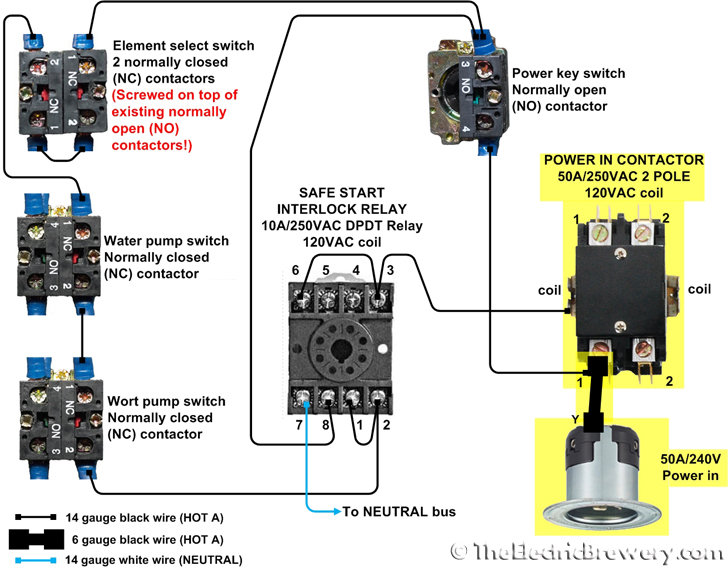
Nothing else in the control panel changes since the rest is all low current 120V. All the switches and how the panel operates remains identical. You just now have twice as much power in each kettle.
Once completed, make sure to follow our control panel setup instructions.
Interested in building your own? Kits are available in our shop.
