Hot Liquor Tank
- Introduction
- Parts and tools
- STEP 1: Coiling the stainless tubing for the HERMS heat exchanger
- STEP 2: Add ball valves for the HERMS coil
- STEP 3: Attach the HERMS coil to the ball valves
- STEP 4: Add the water input ball valve
- STEP 5: Add a water output tee connection for the temperature probe
Introduction
Making beer requires the use of a lot of hot water, often at very specific temperatures. We use 'strike' water to soak or 'mash' grain at very specific temperatures to release sugars and then later use 'sparge' water to rinse off the sugars. This where the Hot Liquor Tank (or HLT) comes in: It's our source of hot water that eventually becomes beer. In brewing terms, the hot water is called 'liquor', hence the name 'Hot Liquor Tank'. In case it's not obvious yet, brewing is full of all sorts of odd-ball terms just to make things more confusing for the new brewer.
We also use the HLT to maintain very specific temperatures as the grain is soaked or 'mashed'. This is done through a heat exchanging coil that sits in the HLT that's been given the fancy name of 'HERMS' (Heat Exchanged Recirculating Mash System) by brewers. We set the desired temperature on our control panel and as the grain is soaked in the Mash/Lauter Tun (MLT), the liquid or 'sweet wort' is pumped through this coil in the HLT to compensate for heat loss that occurs over time.
The Hot Liquor Tank (HLT) is used to heat water. Grain in the Mash/Lauter Tun (MLT) is mixed with hot water. The resulting liquid is recirculated through a HERMS coil in the HLT to maintain temperature. 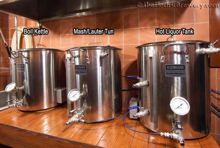
Brewing consistent beer batch after batch is all about having a process that is easily repeatable. One of the hardest aspects in brewing to repeat with most setups is consistent temperatures. With our setup we set the desired mash temperature and walk away. It's that simple. We completely ignore all of the variables that affect mash temperature such as:
- The amount of grain and the temperature of the grain
- The amount of strike water and the temperature of the strike water
- The ambient (air) temperature
- The temperature, size, composition of the container we mash in
- Temperature losses over time due to stirring, poor insulation, etc.
Our setup also ensures that we can precisely control the ratio of water to grain (called the 'mash thickness') in order to create the intended flavour profile. We never add hot or cold water to increase or decrease the temperature so the mash thickness stays consistent. Mash thickness is not one of the most critical factors in brewing but it's one of the many factors that when controlled correctly can take what would normally be considered a 'good' beer to 'great'.
It may seem confusing now but all this will become clearer later when we show the entire setup in action and provide step by step instructions for use (see our Brew Day: Step by Step article). For now, let's build the HLT! The heating element should already have been added to your HLT as per our Heating Elements article. The instructions below will now show you how to install the HERMS coil with two ball valves, a water input ball valve at the top of the kettle, and a tee connection on the kettle output for a temperature probe.
Parts and tools
The following parts are needed:
- (Qty: 50 feet) Stainless steel tubing, 1/2" OD, 0.020-0.035" wall thickness
- or -
(Qty: 1) Custom HERMS coil and 12" long piece of stainless steel tubing, 1/2" OD, 0.020-0.035" wall thickness - (Qty: 4) Stainless steel male quick disconnect 1/2" NPT male
- (Qty: 3) Stainless steel ball valve 1/2" full port
- (Qty: 3) Stainless steel 1/2" NPT lock nut
- (Qty: 4) Stainless steel nipple threaded 1/2" x close NPT
- (Qty: 2) Stainless steel 1/2" compression x 1/2" NPT female fitting
- (Qty: 1) Stainless steel 1/2" compression x 1/2" NPT male fitting
- (Qty: 1) Stainless steel full coupler 1/2" NPT female
- (Qty: 1) Stainless steel street elbow 1/2" NPT female x 1/2" NPT male
- (Qty: 1) Stainless steel tee 1/2" NPT female
- (Qty: 3) Silicone high temperature o-ring (13/16" ID, 1-1/16" OD, 1/8" thick, AS568A Dash No. 211, Durometer hardness A70, FDA compliant, -65F to +450F)
- (Qty: 3) Stainless steel washer/shim (1-1/8" ID, 1-5/8" OD, 0.062" thick)
- (Qty: 3) Stainless steel washer/shim (7/8" ID, 1-3/8" OD, 0.062" thick)
- (Qty: 1) Stainless steel bushing (reducer) 1/2" NPT male x 1/4" NPT female*
You'll also need the following tools:
- GreenLee 13/16" round chassis or radio (not conduit/pipe) punch for making 13/16" diameter holes
- GreenLee 36414 1-3/8" step drill bit
- Hand drill
- Adjustable wrench
- Cutting fluid
- Sharpie permanent marker
-
PTFE white Teflon thread sealant tape
- (Qty: 30-50) Strong (heavy duty) nylon cable tie
- Metal file
-
Hacksaw
- or -
Stainless steel tubing cutter - Tube bender for 1/2" steel
*The bushing (reducer) is only required if a temperature probe with 1/4" NPT thread is used. If the recommended probe with 1/2" NPT thread is used, no bushing is required.
Some sellers do not ship outside the USA. If you live outside the USA (like us), we recommend using a forwarding service such as Shipito. We've used them to ship to Canada. The good news is that shipping within the USA is very inexpensive or often free. You then simply pay a small forwarded fee plus the cost of whatever shipping method you choose (USPS, FedEx, etc.). They will even consolidate multiple packages into one to save on shipping. We recommend USPS whenever possible to minimize brokerage fees.
Purchasing through our affiliate links helps support our site at no extra cost to you. We thank you!
STEP 1: Coiling the stainless tubing for the HERMS heat exchanger
 A 50' piece of 1/2" outer diameter stainless steel tubing is used in the HLT as a heat exchanger to maintain our mash temperature. If 304 and 316 stainless steel are both available, choose 316 as it is a higher grade and is typically used in the food/beverage industry though in our application it really doesn't matter. 316 is a bit harder but for our use both are just as easy (or hard!) to bend.
The wall thickness of the tubing is not overly important. Most stainless steel tubing you'll find has a wall thickness between 0.020 to 0.035" which is perfectly adequate for our application. Our coil is on the upper end of this range and we do not have any issues with heat transfer.
Some will argue that using copper for the HERMS coil would be better given that copper is more efficient at transferring heat than stainless steel. In fluid heat transfers such as in our application, the difference is negligible. Our tests have shown that the temperature of the sweet wort exiting the HERMS coil is always equal to the temperature of water in the HLT so using copper would not have helped. In fact, we found that the two temperatures were always equal even when the temperature of the sweet wort entering the coil was considerably colder that of the HLT water. This was true even when circulating at a reasonably high rate (pump ball valve opened 50-100%).
Stainless steel is easier to clean, stronger, and holds up better over the years with contact with acidic liquids such as beer. We chose to go with stainless steel as much as possible in our setup over other metals such as copper, brass, or aluminum.
Most stainless tubing (including ours) comes in a coil with a diameter that is much too large to fit in the HLT, so we needed to re-coil it. For the best heat transfer the diameter of the re-coiled tubing should place it near the wall of the HLT (though this is not critical). The larger the diameter, the lower the coil will sit in the kettle too which in turn ensures that it remains submerged as much as possible as you use up water from the HLT.
One way to re-coil or bend this 1/2" tubing is to use a manual (hand held) 1/2" tube bender. They're available starting at around $40-50. A tube bender such as the one shown below allows you to make fairly small radius turns of up to 180 degrees but is not great for wide radius turns.

Another option is to take your coil to a machine shop and show them what you want to do. Most shops will have machines to do tube bending quickly and easily and may even do it for free if you mention that it's for making beer. ;)
The tubing may also be re-coiled carefully by hand (and foot) as we did.
Whichever method you choose, be careful not to kink any of the tubing. Kinks cause structurally weak points in the coil that may break over time and also causes flow restriction. Kinking occurs when force is placed in one small location. For this reason some people will find it easier to re-coil by hand as it's nearly impossible to apply force to one small location as long as you're careful.
As we re-coiled carefully by hand, the coil tended to want to spring open so strong (heavy duty) nylon cable ties were used temporarily to hold the form as it was re-coiled. Pictures of the re-coiling process done by hand can be seen below. Go slowly and take your time.
Some hints: Do not attempt to 'bend' the tube such that it stays in the proper shape when released. Instead of 'bending' the tube, we are 'repositioning' the tubing into a different sized radius and then holding it in place temporarily with the cable ties until it is permanently installed in the kettle (at which point the compression fittings take over holding the shape).
 Coiling the HERMS coil has proven to be one of the most difficult aspects of building our brewery for many users, so we've partnered with a US-based stainless tubing company to offer coils professionally manufactured to our specifications. If you're all thumbs, considering purchasing one of these pre-coiled versions.
Before you re-coil your tubing, cut off a 3" piece off one of the ends using a hacksaw and file the edges smooth with a metal file so that there are no burrs. If you want to get a nice clean cut, use a stainless steel tubing cutter instead as it will create a perfect cut without burrs. We're going to use this small piece of stainless steel tubing later as part of our water input ball valve assembly. If you chose to purchase one of the pre-coiled versions, you'll need to supply a short piece of 1/2" OD stainless tubing and cut off a 3" piece.
50' coil of 304/304L (or 316/316L) stainless steel tubing with 1/2" outer diameter: 
The original tubing (as received) with part of it already re-coiled to the right diameter. 
The manual re-coiling process. Strong tie wraps are used every few feet to keep the newly re-coiled tubing in place. These will be removed once the coil is installed in the HLT.
The re-coiling is almost complete:
The finished coil shown beside the HLT for reference:

STEP 2: Add ball valves for the HERMS coil
 We need some way to connect the HERMS coil to the outside of the kettle to allow hoses to be connected so we use stainless quick disconnects with full port ball valves.
The ball valves allow us to close off both the input and output of the coil before disconnecting or connecting a hose.
This is important as we want to make sure we don't end up with up to half a gallon of (possibly hot) liquid on the floor as hoses are connected/disconnected during the brewing process. The 50' long 1/2" inner diameter HERMS coil holds more liquid than you think.
HERMS input/output quick disconnects with ball valves:
 Measure the height difference between the two ends of your HERMS coil as every coil will be slightly different. The coil we made has ends that are 7" apart. We want to place the coil just above the heating element but still as low as possible. Our coil sits approximately 1" above the heating element. The coil is rigid enough to hold itself up without any issues. Keeping the coil as low possible in the kettle ensures that the coil will remain submerged as much as possible as you use up water from the HLT.
In our setup the center of the upper hole is 11.5" from the bottom of the kettle, while the center of the lower hole is 4.5" from the bottom of the kettle.
The left/right placement of these holes is not critical; they don't even have to line up vertically as ours did in our setup. We placed ours approximately 2" to the left of the level gauge (sight glass).
Once you've marked your locations, use a GreenLee 13/16" punch to create two 13/16" diameter holes for the ball valves. Refer to
Step 4: Punch a hole in the kettle from the Heating Elements article for instructions on how to properly create clean holes using a punch like this. Do not use step bits or drills bits exclusively as they do not create nice clean holes.
Position of the 13/16" diameter holes for the HERMS coil ball valves (make sure to confirm the height (7” in our case) with your exact HERMS coil before punching your holes):
Wrap the threaded ends on the quick disconnect and the closed nipple with PTFE white Teflon thread sealant tape to ensure a tight, leak-free fit. Use approximately 6 wraps and always wrap in the direction of the thread so that when the parts are screwed together it does not unwrap. Confused? Watch the video below to learn the correct way of applying PTFE Teflon tape if this is the first time you've used it.
The quick disconnect and closed nipple are first wrapped with PTFE white Teflon thread sealant tape: 
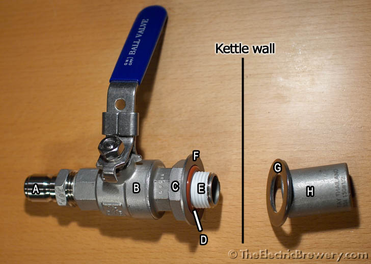
Attach the two ball valves and associated hardware to the inside/outside of the kettle as shown in the picture below. Be careful to place the lock nut (part C) with the inner groove towards the kettle wall. The silicone o-ring (part D) will partially sit inside this groove to avoid being overly compressed between the lock nut and the kettle wall.
Breakdown of the HERMS ball valve connections:
(A) Stainless steel male quick disconnect 1/2" NPT male
(B) Stainless steel ball valve 1/2" full port
(C) Stainless steel 1/2" NPT lock nut
(D) Silicone high temperature o-ring (13/16" ID, 1-1/16" OD, 1/8" thick)
(E) Stainless steel nipple threaded 1/2" x close NPT
(F) Stainless steel washer/shim (1-1/8" ID, 1-5/8" OD, 0.062" thick)
(G) Stainless steel washer/shim (7/8" ID, 1-3/8" OD, 0.062" thick)
(H) Stainless steel 1/2" compression x 1/2" NPT female fitting

Tighten the parts using a wrench until the whole assembly is firmly attached to the kettle wall. You should not be able to twist, turn, or move it at all by hand. Do not be afraid of overtightening as the silicone o-ring cannot be overcompressed.
When finished, the ball valves should feel as if they are welded directly to the kettle and be very stable and secure, exactly like the Blichmann ball valve that is included with the kettle. This should not come as a surprise as we are using the same weldless techniques that Blichmann uses to attach our ball valves.
Once attached we closed both ball valves and filled the kettle up past the highest valve to ensure there were no leaks.
Testing for leaks: 
Draining the kettle after testing:
STEP 3: Attach the HERMS coil to the ball valves
The HERMS coil is now attached to the compression fittings inside the kettle.
Loosen the compression fittings, slide the coil ends in, and then tighten securely with a wrench to create a nice tight connection. These compression fittings (as the name implies) simply hold by compressing a ring against the stainless tubing as the compression fitting is tightened. Teflon tape should not be used.
The compression side of the fittings (the nut farthest from the kettle wall) should be tightened down on the coil until finger tight and then a wrench should be used to turn it another full rotation or so to swage (compress) the ferrules inside onto the coil tubing. This forms the tight seal. Be aware that once swaged, the ferrule cannot be moved or reused.
Remove the nylon cable ties. The HERMS coil will be suspended by the compression fittings, approximately one inch above the heating element (exact distance is not critical).
The finished HERMS coil installed in the HLT.
A close-up of the HERMS coil attached to the compression fittings: 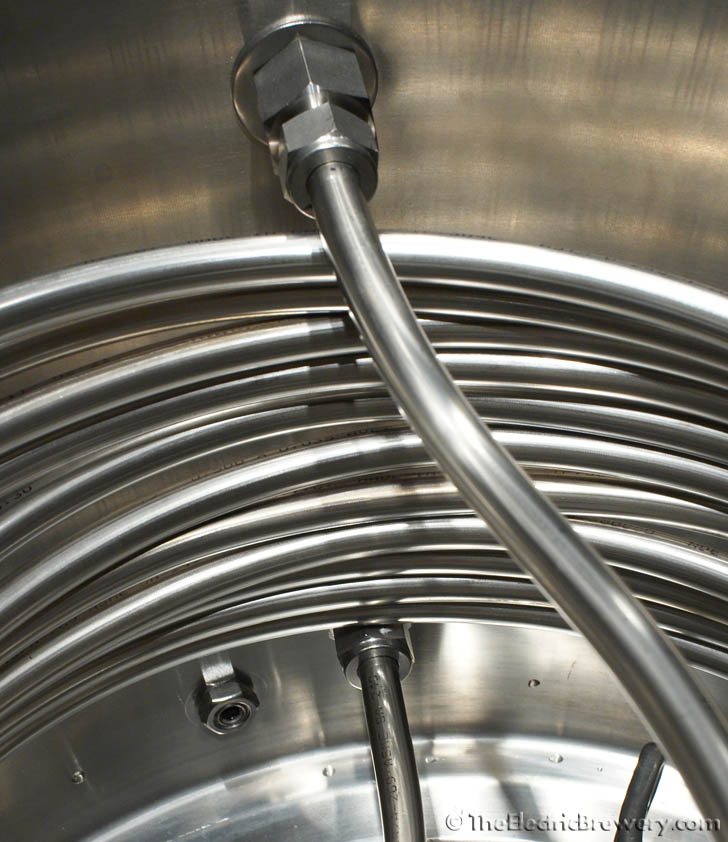
STEP 4: Add the water input ball valve
As the water in the HLT is heated by the element it is recirculated by a pump to ensure that the temperature is consistent throughout the HLT. This movement also helps with heat transfer through the HERMS coil as the hot water will be flowing from the top of the kettle downwards, while the sweet wort in the coil will be flowing from the bottom of the coil upwards.
The water exits out the dip tube and ball valve at the bottom of the HLT. This dip tube and ball valve came with the kettle so there is no need to add them. What we need to add now is a water input ball valve to the top of the kettle.
In our setup the center of the water input ball valve is approximately 2" from the top of the kettle and approximately 4" from the handle.
Water input quick disconnect with ball valve: 
The parts outside the kettle for the water input are identical to what we used for the HERMS coil quick disconnects and ball valves:
The parts inside the kettle are different as we divert the water downwards at an angle so that it circulates around the HLT wall:

Like before, use a GreenLee 13/16" punch to create a 13/16" diameter hole for the ball valve. Wrap all threaded ends first with PTFE white Teflon thread sealant tape to ensure a tight, leak-free fit. Then attach the ball valve and associated hardware to the inside/outside of the kettle as shown in the pictures below. Again, be careful to place the lock nut (part C) with the inner groove towards the kettle wall. The silicone o-ring (part D) will partially sit inside this groove to avoid being overly compressed between the lock nut and the kettle wall.
Breakdown of the water input ball valve connections:
(A) Stainless steel male quick disconnect 1/2" NPT male
(B) Stainless steel ball valve 1/2" full port
(C) Stainless steel 1/2" NPT lock nut
(D) Silicone high temperature o-ring (13/16" ID, 1-1/16" OD, 1/8" thick)
(E) Stainless steel nipple threaded 1/2" x close NPT
(F) Stainless steel washer/shim (1-1/8" ID, 1-5/8" OD, 0.062" thick)
(G) Stainless steel washer/shim (7/8" ID, 1-3/8" OD, 0.062" thick)
(H) Stainless steel full coupler 1/2" NPT female
(I) Stainless steel street elbow 1/2" NPT female x 1/2" NPT male
(J) Stainless steel 1/2" compression x 1/2" NPT male fitting
(K) 3" piece of 1/2" stainless steel tubing (from Step 1)


Tighten using a wrench until the whole assembly is firmly attached to the kettle wall. The short piece of stainless tubing should point down at approximately a 45 degree angle. This will cause the returning hot water to circulate around the kettle which helps with heat transfer through the HERMS coil. The parts you use to divert the hot water downwards are not critical. Feel free to substitute parts (I), (J), and (K) in the picture above with any other stainless parts you have handy.
The compression fitting side of part (J) should be tightened until finger tight and then a wrench should be used to turn it another full rotation to swage the ferrules inside onto the tubing, forming a tight seal.
STEP 5: Add a water output tee connection for the temperature probe
As the water exits the HLT out the ball valve at the bottom, a probe continuously sends a water temperature reading back to our control panel. The control panel then fires the heating element as required to maintain the exact water temperature we set.
 In process control systems such as ours that involve fluid recirculating, temperature monitoring is usually done in the plumbing instead of in the kettle. This helps avoid temperature misreads due to stratification (layering).
The temperature probe we use comes with a cable that disconnects from the probe, making cleaning of the kettle much easier.
We use an RTD (resistive thermal device) temperature probe. Thermocouple based temperature probes are also readily available and are often used in brewing setups. While either will work, an RTD will typically be more accurate and remain more accurate (offer better linearity) over the brewing temperature range we use. RTDs also remain more accurate over time (less drift which means less re-calibration). The cost difference between the two is negligible in our setup.
Our last step is to install a tee connection to make room for this temperature probe as well as a quick disconnect so that hoses may be attached.

Breakdown of the water output tee connection parts:
(A) Stainless steel nipple threaded 1/2" x close NPT
(B) Stainless steel tee 1/2" NPT female
(C) Stainless steel male quick disconnect 1/2" NPT male
(D) Stainless steel bushing (reducer) 1/2" NPT male x 1/4" NPT female*
*Only required if a temperature probe with 1/4" NPT thread is used. If the recommended probe with 1/2" NPT thread is used, no bushing is required.
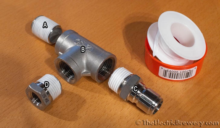
Wrap all of the threaded ends with PTFE white Teflon thread sealant tape to ensure a tight, leak-free fit. Tighten using wrenches until the whole assembly is firmly attached to the kettle ball valve. Two wrenches are required: One to hold the ball valve steady to avoid it turning, the other to tighten the parts we're attaching.
There you have it! Your HLT is done!
Continue on to Building Your Brewery - Mash/Lauter Tun.
