Pumps
- Introduction
- Parts and tools
- STEP 1: Attach the locking plug
- STEP 2: Add quick disconnects and ball valve
- STEP 3: Build a pump stand
Introduction
 We use two March 809/815 pumps with stainless steel pump head housings in our brewery.
This is a tough little pump with a 1/25 hp, continuous-duty 1.4 Amp motor which can be run non-stop for extended periods.
It has no problems handling boiling liquids as the pump is rated to 250F.
We'll be using these pumps to:
- Recirculate water in the Hot Liquor Tank (HLT).
- Transfer strike water from the Hot Liquor Tank to the Mash/Lauter Tun (MLT).
- Recirculate sweet wort in the Mash/Lauter Tun.
- Transfer sparge water from the Hot Liquor Tank to the Mash/Lauter Tun.
- Transfer sweet wort from the Mash/Lauter Tun to the Boil Kettle (BK).
- Transfer wort from the Boil Kettle to the wort chiller and on to the fermenter.
Some of these tasks are done simultaneously (1 & 3, and 4 & 5), hence the requirement for two pumps.
We chose to use stainless steel pump head housings (instead of the more common plastic/polysulfone housings) as the stainless ones are nearly indestructible. Stainless steel is used in professional setups because it is a durable, food-grade metal that can withstand caustic chemicals and can be effectively sanitized.
The pump's magnetic drive acts as a clutch allowing us to put backpressure on the pump to control liquid flow. We do this by placing a ball valve on the output (never the input!) of the pump. This is one major advantage of a magnetic drive pump: They are perfectly safe to run with the output completely blocked, completely stopping the flow of liquid. You won't harm the pump motor.
One disadvantage of magnetic drive pumps however is that they are not self-priming (they cannot clear air in the input lines by themselves). This means that these pumps must be placed lower than the liquid source so that gravity feeds the pump. The liquid sources in our setup are the three kettle outputs on top of our brew stand. Our pumps sit on the lower shelf so gravity feeding is easy.
These stainless pump heads also have a larger 3/4" center positioned inlet (as compared to the usual 1/2" bottom-positioned inlet) which makes priming even easier still. We have never had any issues with priming our pumps. We simply open up the ball valves and liquid flows straight into the pump head. The pump is then turned on and liquid is pushed up and out. A common complaint from brewers with standard 1/2" inlet pumps is that they require extra work to prime through specially installed bleeder valves and/or by playing with the hoses.
While these pumps come pre-lubricated from the manufacturer, they should be lubricated again every year or two.
The pumps are positioned below the kettles making priming quick and painless:
Our pumps come with a bracket so that they can be mounted. We'll be mounting the pumps, attaching quick disconnects and a ball valve, and then replacing the power cord plug with a locking plug to avoid accidental disconnection. Cord length can vary between pump manufacturers, usually from 3-6 feet. Ours are 6 feet long and are just long enough to reach the control panel. Need a longer cord? Add a pump extension cord.
Parts and tools
The following parts are needed:
- (Qty: 2) Pump with high temperature stainless steel housing (3/4" NPT male center inlet, 1/2" NPT male outlet, 115VAC)
- (Qty: 2) Pump extension cord (optional)
- (Qty: 4) Stainless steel male quick disconnect 1/2" NPT male
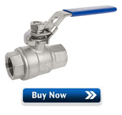
- (Qty: 2) Stainless steel ball valve 1/2" full port
- (Qty: 2) Stainless steel coupler 3/4" NPT female x 1/2" NPT female
- (Qty: 2) Stainless steel street elbow 1/2" NPT female x 1/2" NPT male
- (12 feet) 1/4" expandable braided sleeving - carbon colour
- (2 feet) 3/8" black heat shrink tubing
- (Qty: 2) NEMA L5-15 (125VAC, 15A) twist lock electrical male plug
- (Qty: 2) 1/4" diameter plastic clamps
- (Qty: 17) #8 x 1.5" flat head wood screw
- (Qty: 2) 9 inch long piece of 2x6" softwood lumber (left over from the brew stand build)
- (Qty: 3) 6 inch long piece of 1x2" softwood lumber (available at any home improvement store)
- (Qty: 1) 20 inch long piece of 1x10" softwood lumber (available at any home improvement store)
- (Qty: 2) 6x10" rectangular stainless steel sheet (left over from having purchased the Blichmann BoilerMaker kettles)
- (Qty: 8) 3/16" x 1" stove bolts with nuts
You'll also need the following tools:
- 7/64" softwood drill bit
- Hand drill
- Adjustable wrench
- Screwdrivers
- Saw (preferably a miter saw or table saw)
- Heat gun
-
A roll of PTFE white Teflon thread sealant tape
- Wire cutter/stripper
- 946mL can of MinWax pre-stain wood conditioner
- 946mL can of MinWax Rosewood water-based wood stain
- 946mL can of MinWax polyurethane clear semi-gloss
- (Qty: 3-4) Disposable foam brush
Some sellers do not ship outside the USA. If you live outside the USA (like us), we recommend using a forwarding service such as Shipito. We've used them to ship to Canada. The good news is that shipping within the USA is very inexpensive or often free. You then simply pay a small forwarded fee plus the cost of whatever shipping method you choose (USPS, FedEx, etc.). They will even consolidate multiple packages into one to save on shipping. We recommend USPS whenever possible to minimize brokerage fees.
Purchasing through our affiliate links helps support our site at no extra cost to you. We thank you!
STEP 1: Attach the locking plug
We cut the standard 120V/15A plug off the end of the cord and wrapped the wire in 1/4" carbon colour expandable braided sleeving and used about 6" of 3/8" black heat shrink tubing at each end to help ensure that the braided sleeving did not fray. While not required, it gives the wire a nice finished look and helps protect it.
 Slide the expandable sleeving on first followed by the shrink wrap tubing. Apply heat using a heat gun to shrink the tubing.
A new NEMA L5-15 (125VAC, 15A) twist lock electrical male plug was then attached in place of the one we cut off. We chose to use turn-lock or 'locking' plugs as they plug in like any normal plug but then are turned slightly to lock them in place to prevent accidental disconnection. While not absolutely required, it's an added safety precaution.
There are 3 wires inside the cord: Black (Hot), White (Neutral), and Green (Ground).
Referring to the diagram on the right, the green goes to the pin labelled "G" (usually a green screw), the white goes to the pin labelled "W" (usually a silver screw), the black goes to the unlabelled pin (usually a brass screw).
Make sure your wire is held tightly by the plug crimp/strain relief. This ensures that strain isn't placed on the wire screw connectors.
Don't want to cut off the plug? Consider using a pump extension cord.
Expandable braided sleeving, heat shrink tubing, and locking plug installed:
The locking plugs connect to the receptacles labelled WORT PUMP and WATER PUMP on our control panel: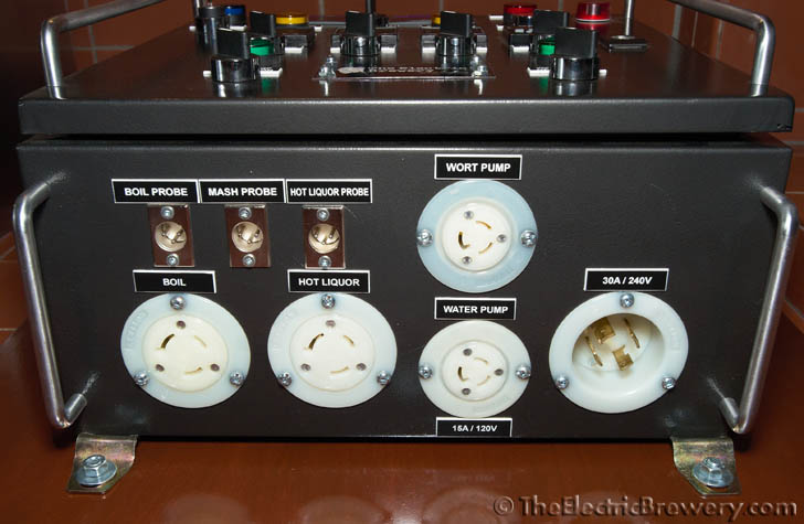

STEP 2: Add quick disconnects and ball valve
 We need to attach a ball valve on the pump output so that that flow speed can be controlled. Male quick disconnects are attached to allow our hoses to be easily connected/disconnected.
We've oriented both disconnects to point horizontally to make hose connection/disconnection easier.
Like in previous instructions, wrap all threaded ends first with PTFE white Teflon thread sealant tape to ensure a tight, leak-free fit.
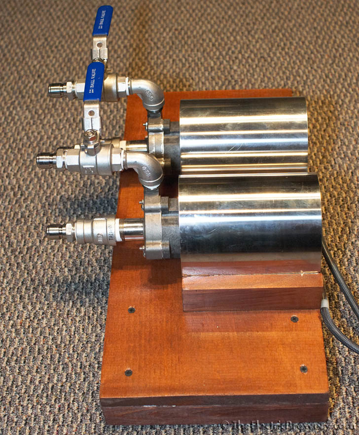
Once threaded, attach the ball valve and associated hardware to the input/output of the pumps are shown below. Both pumps use identical parts.
Breakdown of the pump parts:
(A) Stainless steel male quick disconnect 1/2" NPT male
(B) Stainless steel coupler 3/4" NPT female x 1/2" NPT female
(C) Pump with high temperature stainless steel housing (3/4" NPT male inlet, 1/2" NPT male outlet, 115VAC)
(D) Stainless steel street elbow 1/2" NPT female x 1/2" NPT male
(E) Stainless steel ball valve 1/2" full port

Tighten using a wrench until everything is tight. You cannot overtighten.
STEP 3: Build a pump stand
We chose to attach our pumps to a small wood stand instead of bolting them directly to our brew stand. This makes them portable (in case we want to brew elsewhere) and easier to drain after cleaning (we tip them forward to remove excess water from the pump head).
A 6x10" rectangular stainless steel shield ships with all Blichmann BoilerMaker kettles (to keep heat off the attached Blichmann BrewMometer for those who use them with propane/gas powered setups). We use one shield per pump to create a shroud to partially protect the motors from accidental drips or splashes. (They also provide a nice stainless look to an otherwise drab pump!)
The stand was then stained to match the rest of the brew strand (more information). The pump stand assembly (once the pumps are attached) is heavy enough that it doesn't move around as the ball valves are adjusted.
The pictures below show what we built along with dimensions, but just about any little stand will do. Be creative!
Three 6" pieces of 1x2" lumber attached to the top of a 20" piece of 1x10". Two 9" pieces of 2x6" are used as feet. Held together with #8 x 1.5" flat head wood screws. 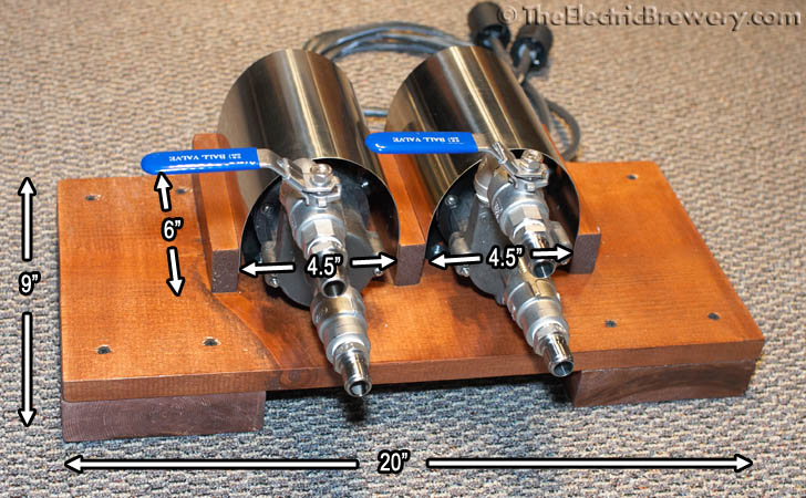
Each pump is held in place with four 3/16" x 1" stove bolts and nuts.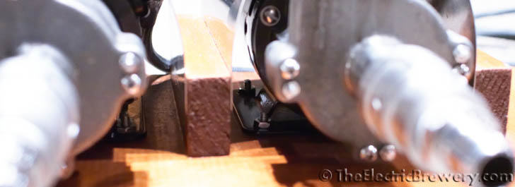
Two 1/4" diameter plastic clamps are used to keep strain off the wire connection point on the motor.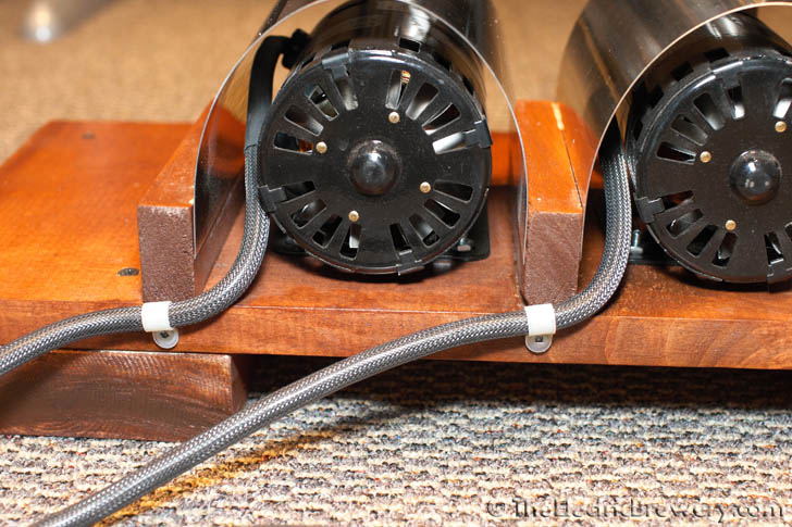
The stainless steel shields are not attached to anything. They're held in place by friction and protect the pump motor from accidental drips or spills while still allowing heat to escape.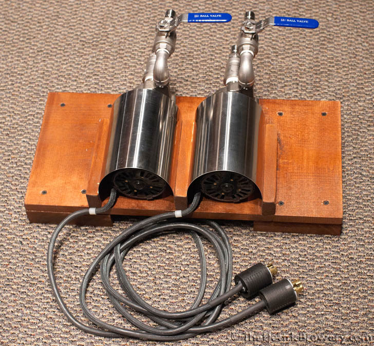
One more step completed. You can now pump stuff!
Continue on to Building Your Brewery - Wort Chiller.
