Control Panel (Part 2)
- Introduction
- Parts and tools
- STEP 1: Supply power
- STEP 2: Build power cord
- STEP 3: Install internal components
- STEP 4: Wiring basics
- STEP 5: Wire up power
- STEP 6: Wire up ground
- STEP 7: Wire up volt and amp meters
- STEP 8: Wire up pumps
- STEP 9: Wire up PID controllers
- STEP 10: Wire up timer and alarms
- STEP 11: Wire up heating elements
- STEP 12: Wall mounting
Introduction
This is part 2 of the control panel assembly instructions.
If you have not already done so, make sure to read part 1 to prepare the enclosure and install the various external components first.
In this part we'll show you how build a power cord to supply power to your control panel, followed by instructions on how to install the various internal components.
Last but not least, we'll show you how to wire everything up correctly, neatly, and safely using easy to follow diagrams (no electrical schematics here!).
Control panel internal components and wiring: 
Parts and tools
To purchase control panels pre-assembled or in kit form, see our order page.
The following parts are needed:
- (Qty: 2) Terminal strip, 8 position, 20 amp
- (Qty: 3) 30A/240V DPDT or DPST relay with 110-120V AC coil
- (Qty: 2) Doorbell transformer (110-120VAC input, 8-24VAC output, any wattage)
- (Qty: 2) Adjustable DC power supply (4-30V AC/DC input, 1.5-27V DC output)
- (Qty: 1) In-line fuse holder for 6.3x32mm fuses, rated to at least 7A/125V
- (Qty: 1) 7A/250V fast blow fuse, glass tube 6.3x32mm
- (Qty: 16) 3/16 x 3/4" stove bolt and nut
- (Qty: 4) 1/8 x 1/2" stove bolt and nut
- (Qty: 4) Small flat rubber washer (1/2" diameter)
- (8 feet) Black 10 gauge type T90/THWN/THHN wire, stranded
- (4 feet) Red 10 gauge type T90/THWN/THHN wire, stranded
- (11 feet) Green 10 gauge type T90/THWN/THHN wire, stranded
- (35 feet) Black 14 gauge type T90/THWN/THHN wire, stranded
- (6 feet) Red 14 gauge type T90/THWN/THHN wire, stranded
- (21 feet) White 14 gauge type T90/THWN/THHN wire, stranded
- (60 feet) 22-24 gauge telephone station or similar low voltage signal wire (rated to 300V)
- (Qty: 25) 22-18 gauge #6 narrow spade terminal (red)
- (Qty: 140) 16-14 gauge #6 narrow spade terminal (blue)
- (Qty: 26) 12-10 gauge ring terminal, #10 hole (yellow)
- (2 feet) 1/2" Spiral wire wrap
- (Qty: 50) Self-adhesive tie mount
- (Qty: 100) Small nylon cable tie
Source of power and power cord:
- (Qty: 1) NEMA 14-30R (125/250VAC, 30A) 4 wire dryer receptacle outlet
- (Qty: 1) 1-gang outlet box
- (?? feet) 10/3 wire with ground (enough to go from breaker panel to dryer outlet)
- (Qty: 1) 30A double-pole GFCI breaker and 4-wire dryer cord
- or -
(Qty: 1) 30A double-pole breaker and 30A/240V cord with built-in GFCI - (Qty: 1) NEMA L14-30 (125/250VAC, 30A) twist lock electrical female connector
You'll also have to supply the following tools:
- Wire cutter/stripper
- Double ratcheting wire crimper
- 30-40W soldering iron or soldering station
- Rosin core solder (63% tin, 37% lead)
- Hand drill
- Drill press
- 3/16" high speed metal drill bit
- Cutting fluid
- Metal file
- Screwdrivers
- Sharpie permanent marker
Some sellers do not ship outside the USA. If you live outside the USA (like us), we recommend using a forwarding service such as Shipito. We've used them to ship to Canada. The good news is that shipping within the USA is very inexpensive or often free. You then simply pay a small forwarded fee plus the cost of whatever shipping method you choose (USPS, FedEx, etc.). They will even consolidate multiple packages into one to save on shipping. We recommend USPS whenever possible to minimize brokerage fees.
Purchasing through our affiliate links helps support our site at no extra cost to you. We thank you!
STEP 1: Supply power
 We need to supply power to our control panel to run the various lights and switches and also allow it to run the pumps and heating elements.
The heating elements are power hungry so more power than what a standard 120V AC 15 amp outlet can provide is required. We need to supply twice the voltage (240V AC) and almost twice the current (30 amps) in order to run all of the devices connected to our control panel.
To provide this extra power we use a standard 4-slot North American clothes dryer outlet as it is capable of providing both 120V and 240V AC at up to 30 amps.
With everything running (including both pumps and one heating element) our current consumption is almost exactly 24 amps. A standard 4-slot North American clothes dryer outlet is therefore perfectly sized in terms of current capacity to run our control panel.
We purposely designed our system to use no more than 30 amps as dryer outlets are easily installed and/or are already available in most homes. It also makes our setup somewhat portable if we wish to bring our equipment with us and brew elsewhere.
Standard 120V AC 15 amp outlet (left) and 240V AC 30 amp dryer outlet (right):
Residential power
In North America, most residential power comes in to the house as 240 Volts AC over 3 wires: Two HOT wires called 'A' and 'B', and a NEUTRAL wire. This power is fed in to your circuit breaker panel which splits it up and feeds it into different circuits throughout the house. The breakers are used to protect the wires in these circuits from overheating. Breakers do not protect the equipment or the people using the equipment.
By connecting (called 'tapping') across different pairs of the three wires we get different voltages:
- 120V AC: By tapping across either of the HOT lines and NEUTRAL for standard household devices such as lights, televisions, computers, etc. Single-pole breakers are used and take up one slot in your breaker panel. Approximately half of the circuit breakers in a house will use HOT 'A', with the other half HOT 'B' in order to try and balance how power is consumed.
- 240V AC: By tapping across the two HOT lines for power hungry devices such as electric stoves, clothes dryers, air conditioning units, baseboard heaters, etc. Double-pole breakers are used and take up two slots in your breaker panel.
Single-pole breaker (left) and Double-pole breaker (right):
We use both voltages in our control panel: 240V AC for our heating elements and 120V AC for all of the other devices (pumps, lights, PID controllers, etc.)
There is a 4th wire too: Somewhere near the house is a rod buried in the ground with a wire attached to it that is connected to the circuit breaker panel. This is the 4th wire used in residential electrical systems and our control panel. It's called the GROUND.
In our brewing setup a ground is used for safety: The GROUND line is electrically connected to the kettles and the control panel enclosure in the same way a power tool or appliance chassis is grounded. In the off chance that something goes wrong and one of the HOT lines becomes disconnected and touches the control panel enclosure or one of the kettles, the GROUND line ensures that any stray current can find its way to ground through a wire instead of through something else (such as the brewer!). Without proper grounding the enclosure or kettle would simply become energized and pose a great danger to you, the brewer. An electric brewing setup should always have everything properly grounded. With proper grounding the current will instead immediately start to flow and trip the circuit breaker, turning off power.
Our standard North American dryer outlet provides all 4 wires that we need (two HOTs, one NEUTRAL, and a GROUND). As mentioned previously, we get 120V AC by tapping across either HOT line and NEUTRAL, and 240V AC by tapping across both HOT lines.
Note that some clothes dryer outlets may be rated for 240V AC / 30 amp use but only have 3 wires (not 4). We do not recommend using these outlets as they are no longer up to code as they have tied (bonded) NEUTRAL and GROUND together. For safety reasons, in most locations today, NEUTRAL and GROUND may only be bonded at the circuit breaker panel.
The standard 4-slot dryer outlet we installed to supply both 120V and 240V AC with ground to our control panel.
Ground Fault Circuit Interrupter (GFCI)
 A GFCI is not to be confused with a circuit breaker found in your electrical breaker panel. Regular breakers are rated for specific current ratings and will switch off (or 'trip') if ever the rated current is exceeded on the circuit they control. The sole purpose of breakers is to protect the wires from overheating.
A GFCI (or more accurately, a residual-current device) on the other hand is not used to protect wires or devices - it protects the equipment operator. A GFCI will cut power when it detects that the current going in to a circuit does not match the current coming out of the circuit. Often this imbalance (typically only a few milliamps) is caused by current leakage through the body of a person who is grounded and is accidentally touching an energized part of the circuit.
The distinction is important: A circuit breaker saves equipment, a GFCI saves lives. GFCIs are designed to prevent electrocution by detecting the leakage current, which can be far smaller (typically 5–30 milliamperes) than the currents needed to operate conventional circuit breakers or fuses (several amperes). GFCIs are intended to operate within 25-40 milliseconds, before electric shock can drive the heart into ventricular fibrillation, the most common cause of death through electric shock.
While the electrical code varies from country to country, in the United States GFCIs are typically required in kitchens, bathrooms, and other places that can be wet and the National Electrical Code (NEC) requires that GFCI devices intended to protect people interrupt the circuit if the leakage current exceeds a range of 4–6 mA of current (the trip setting is typically 5 mA) within 25 milliseconds. In other places the trip setting may be as high as 10-30mA.
A GFCI should most definitely be used in the circuit that powers your brewery control panel. This GFCI can be installed in one of two places: Either in the double-pole 30 amp circuit breaker in the electrical panel, or in-line with the control panel power cord. We recommend that you check that whatever GFCI you intend on using adheres to your local electrical code in terms of trip settings and speed of operation.
Popular amongst electric brewers in the early years of electric brewing (around 2008-2010 time frame) were 240V AC 30 amp GFCI cords that were previously used to power Xerox copy machines as they can sometimes be found on eBay for less than a double-pole 30 amp GFCI breaker. It's important to note however the 30A GFCI cords have a trip setting of 10mA (slightly above the United States NEC requirements).
240V AC 30 amp cord with GFCI built in:
Approximately half a dozen different electrical panel brands exist (Cutler Hammer, Siemens, GE, etc.) so if you purchase a double-pole 30A GFCI breaker make sure that it matches your electrical panel. Refer to a qualified electrician for assistance if required.
Please do not forgo using a GFCI thinking that simply being 'careful' will be enough. Like the seat belts in your car, a GFCI exists because accidents or failures happen, even on properly designed, built, and operated equipment.
Install dryer outlet
DISCLAIMER: Always follow electrical code requirements specific to your area, and before undertaking any home electrical project, contact your local electrical authority and your insurance company to ensure that you comply with all policies, warranties, regulations and authorities concerning this work.
If you don't already have a standard 4-slot 240V AC 30A dryer outlet handy to power your brewery, you're going to have to install one.
Detailed instructions for installing this outlet and corresponding double-pole 30A breaker or double-pole 30A GFCI breaker are not provided on this website. All breaker panels are slightly different and national/regional electrical code may also be slightly different based on exactly where you live.
We recommend that you refer to a qualified electrician if you have any questions on how to safely install a dryer outlet as an electrical breaker panel can be a very dangerous place.
We will, however, provide you with the general steps:
- Cut the electrical breaker panel main power.
- Install a double-pole 30A breaker (with GFCI if your power cord does not include one) in the panel. The breaker must be matched to your panel brand/type as breakers are panel-specific.
- Following electrical code for your area, install a dryer outlet in a conduit box.
-
 Following electrical code for your area, install 10-3 wire (10 gauge wire, three conductors, with ground) between the new double-pole breaker and the dryer outlet.
In the breaker panel the two HOT wires (red and black) are connected to the two breaker HOT poles. If installing a GFCI breaker the NEUTRAL wire (white) from the outlet is connected to the breaker NEUTRAL pole and the white pigtail wire from the breaker is connected to the neutral bus bar in the breaker panel. If installing a non-GFCI breaker the NEUTRAL wire (white) from the outlet is connected directly to the neutral bus bar in the breaker panel. In all cases the GROUND wire (green or bare) is connected to the ground bus bar in the breaker panel.
In the dryer outlet the two hot wires (red and black) are connected to the straight slots (often labelled 'X' and 'Y') with brass screws, the NEUTRAL wire (white) is connected to the L-shaped slot with the silver screw, and the GROUND wire (green or bare) is connected to the D-shaped slot with the green screw. - Re-enable the electrical breaker panel main power and turn on the new double-pole 30A breaker.
- Use a voltmeter to measure the voltage between various points on your new dryer outlet. You should see 120V AC across either HOT and NEUTRAL, 120V across either HOT and GROUND, and 240V AC across HOT A and HOT B. If using a GFCI breaker, press the test button to trip the breaker and re-measure: The 120V AC and 240V AC readings should now be 0V.
4-slot dryer outlet wiring:
STEP 2: Build power cord
We need to build a power cord to get power from our dryer outlet in to the control panel.
Two options are available depending on where your GFCI is located:
- Use a cord with a 30A GFCI built in, or
- Use a standard 4-wire dryer cord (with a GFCI breaker in the electrical panel).
Regardless of the solution you choose, a GFCI should be used.
240V AC 30 amp cord with GFCI built in (17 feet long):
Standard 240V AC 30 amp dryer cord (10 feet long):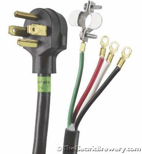
 Both cords are already equipped with a plug for plugging into our dryer outlet. All that's missing is the L14-30 connector on the other end to connect to our control panel.
If you use the 30A GFCI power cord be aware that it uses non-standard wire colours for HOT and NEUTRAL so be careful how you connect it up. Refer to the picture below and hook it up as follows to the L14-30 connector: The two hot wires (black and brown) are connected to the 'X' and 'Y' connectors with brass screws, the NEUTRAL wire (blue) to the 'W' connector with the silver screw, and the GROUND wire (green) to the 'G' connector with the green screw. Cut off any compression ring terminals first - all we need is bare wire.
If you use a standard 4-wire dryer cord the wire colours are typically standard. Refer to the picture below and hook it up as follows to the L14-30 connector: The two hot wires (black and red) are connected to the 'X' and 'Y' connectors with brass screws, the NEUTRAL wire (white) to the 'W' connector with the silver screw, and the GROUND wire (green) to the 'G' connector with the green screw. Cut off any compression ring terminals first - all we need is bare wire.
L14-30 connector used to connect to our control panel: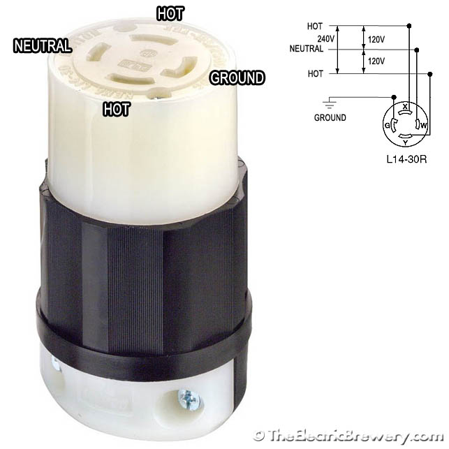
240V 30A power cord with GFCI built in, plugged in to the dryer outlet. The actual GFCI circuitry is in the large grey box with the red 'test' and black 'reset' buttons.
STEP 3: Install internal components
We have 10 components that need to be installed on the back plate:
- Two (2) Terminal strips, 8 position, 20 amp
- Three (3) 30A/240V DPDT or DPST relays with 110-120V AC coil
- Two (2) doorbell transformers (110-120VAC input, 8-24VAC output, any wattage)
- Two (2) adjustable DC power supplies (4-30V AC/DC input, 1.5-27V DC output)
- One (1) 50A shunt (included with the amp meter)
Remove the back plate from the enclosure and lay out all 10 components as shown in the picture below. Exact position is not critical. Mark the mounting holes with a Sharpie permanent marker.
The best way to install components to a back plate is to create threaded holes so that nuts are not required on the back side. This makes future maintenance easier as the entire back plate does not have to be removed to gain access to a nut if a component needs replacing. To create threaded holes you need to use a tap and die set as shown in the installation of our heat sink in part 1. The components are installed using 3/16 x 3/4" stove bolts. The adjustable DC power supplies have parts close to the mounting holes so smaller 1/8 x 1/2" stove bolts were used instead. Drill pilot holes first using a high speed steel (HSS) drill bit. Refer to your tap and die set for the correct size pilot hole for the bolt size you'll be using. Thread the holes using the correct size tap. Go slowly, turning the tap by hand and let the tap do the work. Clean off any metal shavings.
 If you do not own a tap and die set, (Why not? They're inexpensive!), then you may simply drill the holes with a 3/16" high speed steel drill bit and use a metal file to smooth down any rough edges. Make sure to keep any metal filings out of the enclosure. Mount all of the items using 3/16 x 3/4" stove bolts and nuts. The adjustable DC power supplies have parts close to the mounting holes so smaller 1/8 x 1/2" stove bolts were used instead.
Unlike the other components, the DC power supplies cannot be bolted directly against the metal back plate as the circuit board will scratch through the orange paint and cause short circuits. Use small flat rubber washers or an extra nut or two on the bolt between the circuit board and the back plane to keep them separated. Better yet, use nylon standoffs and screws (included in our control panel kits or available separately with our power supplies).
Reinstall the back plate in the enclosure.
10 components are installed on the back plate:
Flat rubber washers are used to keep the DC power supplies from touching the back plane:
A better option for mounting the power supplies is to use nylon standoffs and screws (included in our control panel kits or available separately with our power supplies):
STEP 4: Wiring basics
 Wire comes in various sizes. The larger the size (diameter), the more current it can carry.
Wire size is denoted as 'gauge'. We use the 'American Wire Gauge' (or AWG) sizing in describing wire size in our instructions. The smaller the number, the bigger (not smaller) the wire is and the more current it can carry.
Three sizes of wire are used in our control panel:
- 10 gauge: Used for high power items like the heating elements. The elements draw up to 23-24 amps so large 10 wire gauge must be used.
- 14 gauge: Used for standard items that consume less than 15 amps such as pumps, lights, meters, etc.
- 22 gauge: Used for extremely low voltage/current devices such as the temperature sensors, shunt signal, DC power supplies.
All of the 10 and 14 gauge wire is type T90/THWN/THHN (Thermoplastic High Water-resistant Nylon-coated/Thermoplastic High Heat-resistant Nylon-coated) meant for wet or dry locations. It's typically used for pulling through conduit or in control panels such as ours. We used stranded wire (not solid core) as it is easier to work with.
A roll of 14 gauge T90 THWN/THHN nylon coated electrical wire:
For the 22 gauge low voltage/signal wiring we used various odds and ends we already had on hand.
The wire is small enough that either solid core or stranded may be used easily. Telephone station wire which is typically 24 gauge can easily be used here as it is very inexpensive and provides 4 individual conductors in a variety colours making hook-up easier. Divide the amount required by 4 when using 4-conductor wire such as this. Make sure it is rated to at least 240V.
4-conductor telephone station wire: 
We use different coloured wire to identify the type of voltage or signal carried. We tried as much as possible to follow these standards:
- Black: HOT A line
- Red: HOT B line
- White: NEUTRAL line
- Green: GROUND
- Any other colour: DC or low voltage signals
When a signal is carried by two wires and polarity is important (such as in DC) we'd often include a small piece of black shrink wrap tubing on the end of one of the wires to remind us which end is negative. Hooking up polarized signals backwards is generally not a good thing.
All 4 SSR control wires are the same colour so using heat shrink tubing helps identify negative from positive. 
Most of the components in the control panel use screw terminals. While bare wire could be used, it's more likely that single strands may break off and end up somewhere they shouldn't causing electrical shorts (also not a good thing). So we use compression spade and ring terminals that are crimped on to the wires to simplify wiring up the control panel.
Larger yellow 12-10 AWG ring terminals with #10 hole are used for the 10 gauge wires. Blue 16-14 AWG #6 narrow spade terminals are used for the 14 gauge wires while Red 22-18 AWG #6 narrow spade terminals are used for the 22 gauge wires. Make sure to get the narrow size blue and red spades. The wider ones will not fit in the PIDs or timer.
Some locations (such as the XLR receptacle wires) are soldered on directly.
While ring terminals are more work to install (the entire screw must be removed) we use them for safety reasons with the high current devices. They ensure that the wire will remain in position even if the screw becomes loose by accident.
Compression ring terminals on the left, spade terminals on the right:
A cheap 3-in-1 wire cutting/stripping/crimping tool can be used but we recommend using a separate tool to crimp if you want to do it right.  We recommend splitting the job over two tools as follows:
- A wire cutter/stripper to cut and strip the wire: If using a non-adjusting cutter/stripper, be careful to use the correct size notch when stripping to avoid cutting any of the strands which would effectively reduce the wire gauge. If you're all thumbs consider a self-adjusting wire cutter/stripper which does some of the work for you.
- A double ratcheting terminal crimper to attach the terminal to the wire: These crimp in two spots at once which saves time and creates a better connection as they apply force continuously and evenly. They also save your hands from lots of pain.
Spiral wire wrap is used where bundles of wires pass from the back plate to the door. The spiral wrap prevents the wires from rubbing whenever the door is opened or closed and also prevents it from getting snagged on the various components.
Compression ring and spade terminals are used for connecting wire to components. Spiral wire wrap helps protect wiring from abrasion.

Self-adhesive tie mounts and nylon ties are used throughout the control panel to help keep the wiring clean and tidy.
They are used for more than just aesthetic purposes: They help keep wires away from controls, heat producing parts, and door hinges.
The trick to using tie mounts is not to be too stingy - use them liberally. They are only a few dollars for a bag of 100. Use them every few inches and whenever there are twists and turns.
We recommend installing the tie mounts and nylon ties before wiring starts. Simply leave the ties as large loops and pass the wires through as you work. Once everything is tested and working, tighten down the ties and cut off the loose ends.
Self-adhesive tie mounts and nylon ties:
STEP 5: Wire up power
 A key operated selector switch is used to power the control panel. The control panel can only be powered up if the key is inserted and turned.
While a key operated switch is certainly not a requirement, it helps keep curious hands from being able to do any damage and also stops any unauthorized brewing. (Ok, that last one was a bit of a stretch).
When the key power switch is turned to the on position, the blue LED pilot light turns on to let us know we have power.
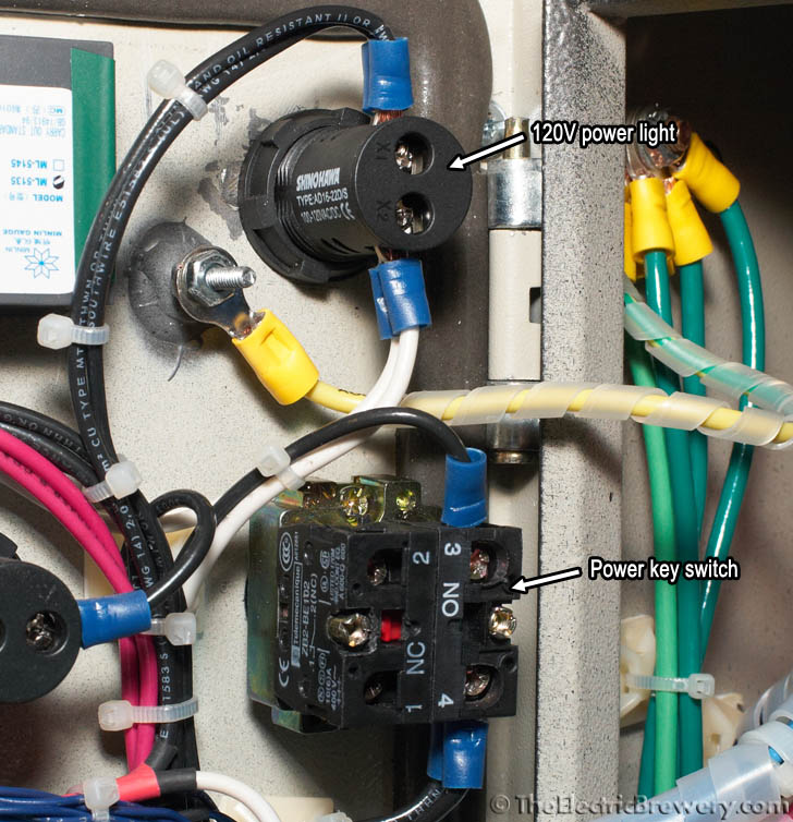
The main control panel power switch requires a key. No unauthorized brewing!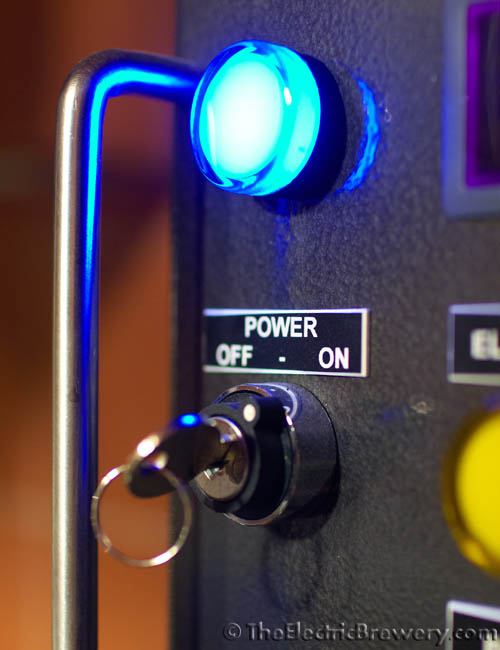
 Most small switches such as this one cannot handle the large amounts of current required by our system so current does not actually flow through the key operated power switch. Instead, the power switch is simply used to control a large relay which is capable of handling up to 30 amps. A relay is simply an electrically operated switch. Turning the power switch to the on position activates a coil in the relay which closes contacts able to handle up to the 30 amps of current we require. Current is then able to flow into the rest of the control panel to power the other devices including the high power devices like the heating elements.
Generally speaking, high power switching such as this is always controlled remotely in electrical panels where a smaller 'control' switch on the door is used to activate a larger switch (such as a high power relay or a definite purpose contactor) that is permanently installed on the back plate. This is done for ergonomic reasons (smaller switches are easier to operate) and for safety reasons (high power wires are not required to move or bend when the door is opened/closed).
Since this is the first wiring diagram, here are some hints:
- White (NEUTRAL) wires are shown as blue in our diagrams.
- When orientation is not important, it is not shown. For example, it does not matter which side of the 120V power light connects to the HOT or NEUTRAL bus nor does it matter which way wires are connected to the power key switch NO contactor or on which side of the switch the contactor is installed. In some cases orientation is extremely important: For example, The 14 gauge neutral wire must connect to the "W" (NEUTRAL) screw on the 30A/240V power in receptacle while the larger 10 gauge black wire must connect to the "Y" (HOT A) screw.
- You may notice what appears to be extra wires in some of the close-up photos when compared to the wiring diagrams. This is normal. For example, in the wiring diagram immediately below the 120V power light connects to the HOT and NEUTRAL bus only (2 wires, one black, one white) but in the photos further below there are 4 wires. This is because other parts that need to be wired to the HOT and NEUTRAL bus later on were wired to the two sides of the 120V power light instead. The result is the same. There's no need to send 10 pairs of wires all the way back to the buses each time.
- The HOT and NEUTRAL buses are simply connection points where multiple wires are tied together. In the power input wiring diagram below we show an example of how this can be accomplished. Which screws on the bus are used for the connections does not matter, but all wires connected to the bus must be tied together using short wire jumpers or pre-made terminal strip jumpers as the 8 small metal bars that make up the buses are not connected electrically. When connecting a wire, simply choose a free screw and then make a short wire jumper (or use pre-made terminal strip jumpers) to connect the new wire to the others on the bus. As mentioned in the previous bullet, if the component you wish to connect to a bus is close to another component that is already connected to the same bus through an existing wire, you may simply connect the two components together to save on wiring. In future wiring diagrams, these buses will not be shown in order to make the diagrams easier to read. Instead, we will simply indicate which bus a wire must connect to with an arrow and some text.
Wire up the components as shown in the diagram below using the wire sizes and colours indicated.
Power input wiring diagram: 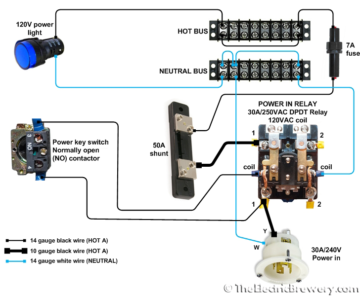
How it works
With the power key switch off, power is completely cut off from the rest of the control panel. Only the power switch itself is energized.
Turning the power key switch ON allows 120V to pass through the relay coil which closes the relay contacts (making a satisfying 'clunk' noise). This allows power from both the HOT A and HOT B lines to flow into the control panel. One HOT is used to energize the HOT bus which turns on the blue 120V power light.
We used a DPDT (double pole, double throw relay) which is essential two switches (poles) with two settings each (throws). We only use one of the throws in all our DPDT relays so DPST (double pole single throw) relays could also be used but are generally harder to find.
 The 30A breaker in our circuit breaker panel protects all 10 gauge wire right up to and inside our control panel. The 7A fuse in the in-line fuse holder is used to protect the smaller 14 gauge wire. Later on we'll be drawing power off the large 10 gauge wire before the fuse to run our power-hungry heating elements.
The 50A shunt is basically a large wire with a precisely known very low resistance (1.5 milliohms in our case). The amp meter measures the voltage drop across the shunt (0.075V max) to display the current used by our control panel. The tiny voltage drop does not affect the other equipment in the panel.
 Many of the lower power devices in the control panel are powered off the HOT (black) and NEUTRAL (white) wires so two 8 position terminal strips are used as common connection points (known as 'buses'). The 8 positions are not wired together by default so short jumper wires are used as shown in the diagram above. You may also use pre-made terminal strip jumpers. In future diagrams we will simply indicate when a wire must be connected to one of the two buses without showing the entire bus. It's up to you to create the short jumpers and make sure that all the HOT or NEUTRAL wires are joined together.
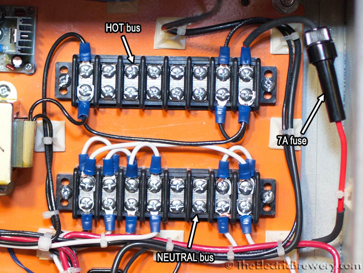
Location of the components: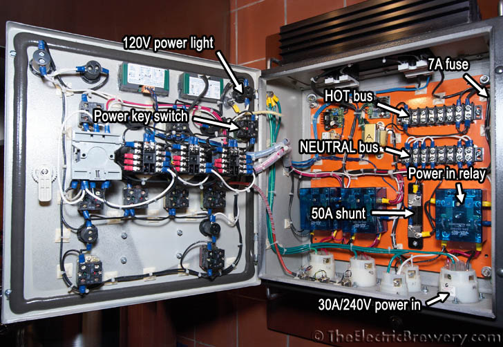
Close-ups: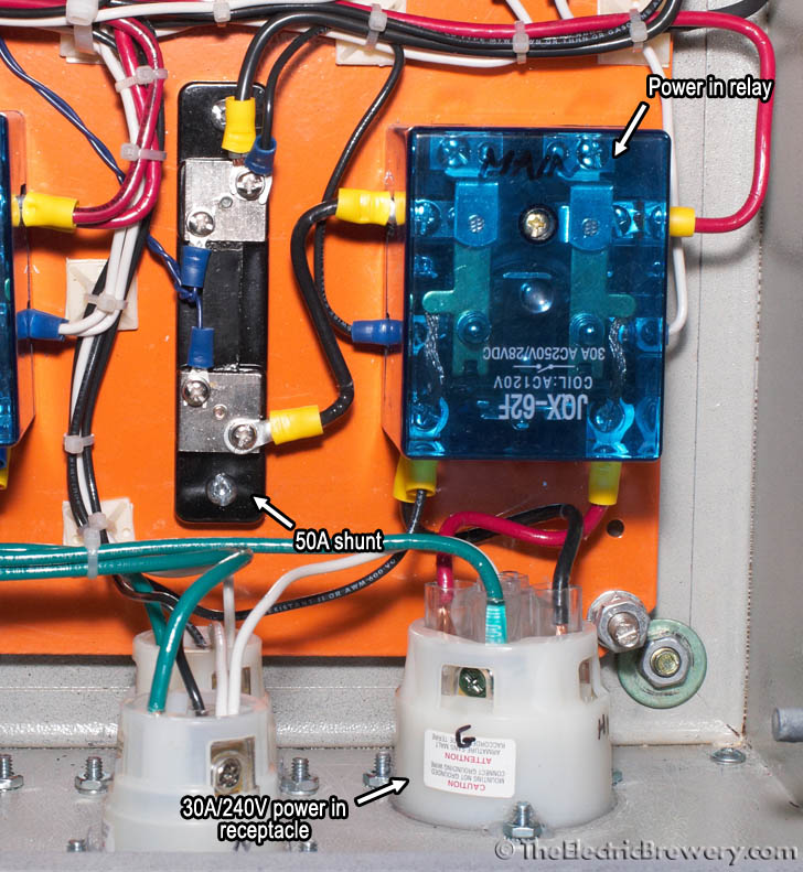
STEP 6: Wire up ground
We want the control panel enclosure chassis to be electrically grounded for safety reasons the same way any power tool or appliance chassis is grounded. Grounding means that the entire metal chassis (in this case the entire enclosure) is connected to your house's electrical system ground plane. This ensures that any stray current can find its way to ground instead of through something else (such as the brewer) in the off chance that something goes wrong and one of the HOT wires becomes disconnected and touches the enclosure.
Without proper grounding the control panel enclosure would instead simply become energized and pose a great danger to you. A proper electric brewing setup should always have everything properly grounded.
Wire up the components as shown in the diagram below using the wire sizes and colours indicated.
Ground wiring diagram: 
How it works
There are two ground points in the control panel: One on the door (which we moved earlier) and one in the main enclosure. We connect these together using the ground wire that was included with the enclosure. This ensures that both the door and the main enclosure will be grounded.
We then ground the enclosure to the Hot Liquor Tank and Boil kettles through the heating element receptacles, to the wort and water pumps through the pump receptacles, and finally to the ground in the house circuit breaker panel through the 30A/240V power in receptacle.
Every metal part in the brewery that contains power is now properly grounded to our house ground.
Each ground wire is separate (called a 'home run') to ground for safety reasons.
Location of the components:
Close-ups:

STEP 7: Wire up volt and amp meters
 The volt and amp meters are used to display the voltage being fed to the panel and the current consumption. Neither are truly required for the brewing operation. They simply give us piece of mind that things are operating as expected.
Our control panel is fed by a 30 amp circuit in our house. With everything running (including both pumps and one heating element) our current consumption is almost exactly 24 amps.
The voltage fluctuates throughout the year and based on the time of day. It's not uncommon to see the voltage sag (drop) by 5-8% during the hotter summer months when everyone is running their power hungry air conditioners. Voltage sags do not affect the brewing process.
Volt and amp meters display the voltage being fed to the panel and the current consumption:
Wire up the components as shown in the diagram below using the wire sizes and colours indicated. Make sure that the wire you use to connect to the AC inputs on the volt meter is rated to at least 240V. Most 4-conductor telephone station wire is rated to 300V which is perfect.
The doorbell transformers may include wiring that is slightly different than what is shown in the diagram below. Often the low voltage side will use screws as connection points instead of wires. If more than two connection points are available, the transformer offers more than one output voltage. In such cases connect wires to the two connection points that will supply approximately 16V. Connect the other ends of these two wires to the AC IN points on the power supply (polarity does not matter). If the transformer includes a green (ground) wire, connect it to the enclosure ground post or any other part of the control panel that is grounded, such as the back plate. Polarity of the high voltage side wires that connect to the HOT and NEUTRAL buses does not matter.
Using an adjustable power supply lets us adjust the brightness of the meters to match the rest of our lights. The location of the adjustment potentiometer is indicated by the yellow arrows in the wiring diagram (see below). Turn both counter clockwise for 20-30 revolutions to make sure the output voltage is initially set very low before using them for the first time, then slowly increase the voltage until the meter brightness matches the 120V blue power light. If you have a multimeter handy, we find that for our meters setting the power supply to around 4.5 - 4.7V DC output works best. Different brand meters may give different results; however, some may not run reliably under 5.0V DC. When in doubt, set to the output to 5.0V DC but no higher. Too high of a voltage may destroy the meters.
WARNING! Always confirm the connection points on the transformers, power supplies, and meters with the documentation that was supplied or by referring to the labels directly on the device itself. Your devices may use connections that are slightly different from the ones shown here. For example, do not assume that the left most connection on the back of the volt meter is for +5V DC. The manufacturer may have changed the pinout or you may have purchased a slightly different version than the one we use here. Always confirm and read the labels that are provided with the devices you install before attaching wires and turning on the power. Failure to do so can easily destroy the meters.
Volt and amp meter wiring diagram: 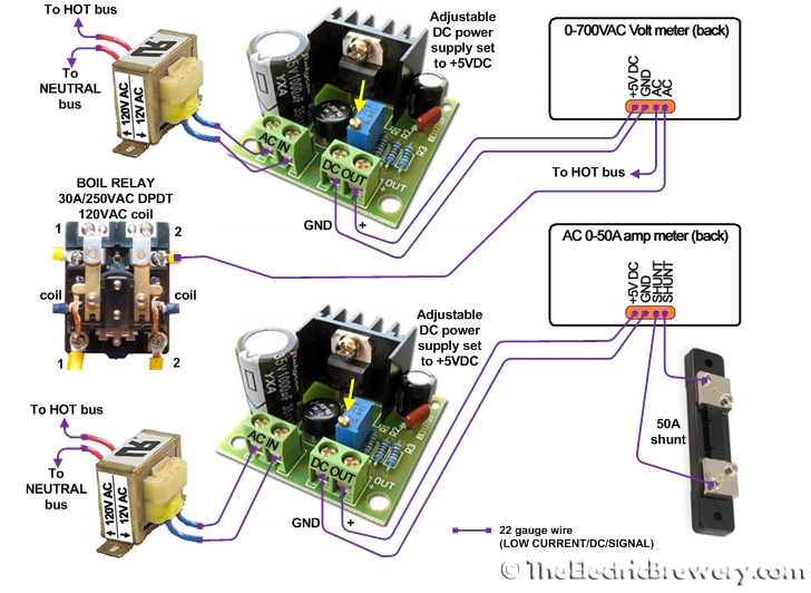
Meter labels will vary by manufacturer. Below are the meters we use with our control panels, with the connection points labelled to match those found in our wiring diagram:
For doorbell transformers that offer more than one output voltage, use the two connection points that offer 16V (the two rightmost screws in the picture below):![]()
How it works
 Both meters require 5 volts DC to operate. We use small 10:1 step-down transformers (doorbell transformers work perfectly) to take 120 volts AC down to 12 volts AC followed by small adjustable DC power supplies (AC 4V-30V input, DC 2.5V-27V output
![]() Because of the way this particular volt meter is designed (one of the AC inputs is tied to the DC ground), separate power supplies and transformers must be used in order to isolate the meters from each other. Trying to use one power supply and transformer to power both meters will destroy the meters (ask us how we know!) even through the supplied instructions say this is possible.
Because of the way this particular volt meter is designed (one of the AC inputs is tied to the DC ground), separate power supplies and transformers must be used in order to isolate the meters from each other. Trying to use one power supply and transformer to power both meters will destroy the meters (ask us how we know!) even through the supplied instructions say this is possible.
The volt meter can measure up to 700 volts AC and is connected directly across the two 120 volt AC lines (HOT A and HOT B) that produce a differential of 240 volts AC.
The amp meter can measure up to 50 amps AC. This large amount of current does not directly flow through the amp meter. Instead, a 50A shunt is used with a precisely known resistance (1.5 milliohms in our case). Current passes through the shunt and the amp meter measures the associated voltage drop (0.075V max) and translates it into amps. Amp meters and shunts are typically matched and sold in pairs.
The shunt is located immediately after the main power relay so that it measures all current that flows through the control panel.
Location of the components:
Close-ups:

STEP 8: Wire up pumps
 We use two pumps in our brewery. We use one for pumping wort while the other is used for pumping water, hence the names "wort pump" and "water pump".
Our control panel has an on/off selector switch for each. When on, the 120V green pilot light turns on and power is supplied to the pump receptacle.
Pretty simple!
Pump switches and lights: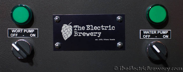

Wire up the components as shown in the diagram below using the wire sizes and colours indicated.
Pump wiring diagram: 
How it works
The pump wiring is very straight forward: The on/off selector switches control the flow of power to the 125VAC/15A receptacles and the 120V green LED pilot lights.
The sets of receptacles and lights are wired in parallel, which ensures that both receive 120V AC.
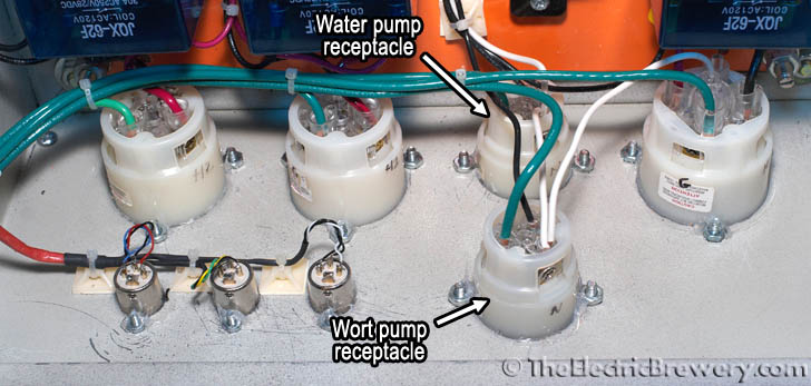
Location of the components:
Close-ups: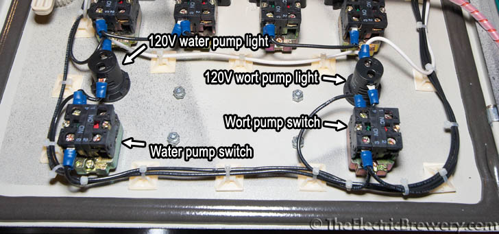
STEP 9: Wire up PID controllers
 A PID controller (proportional integral derivative controller) is a control loop feedback device that is used to continually calculate the difference between the target temperature and the measured temperature and takes the appropriate action to make up for any difference.
A PID controller is an intelligent device that learns and trains itself to the behaviour of a system so as to not overshoot or undershoot the target temperature. It is more advanced than most simple temperature controllers (such as those from Love Controls) that only look at the temperature. A PID controller also considers the rate of change of temperature. This means that as a PID controller sees the target temperature approaching, it knows to "slow down" so that it doesn't overshoot the temperature. A PID controller uses calculus to measure this rate of change instead of simply looking at "am I too high or too low?".
The end result is a more consistent temperature, one that doesn't continually oscillate over and under the target temperature. The good news is that the PID controller does it all automatically for us. We don't have to have any understanding of how this all works (no need to remember your high school calculus).
The SYL-2352 PID controllers we use incorporate more advanced fuzzy logic as compared to some simpler PID controllers for even greater control. In our brewery when we set the target temperature, the liquid ramps up to that temperature and stays there. That's really all we care about.
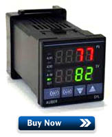
Our three PID controllers: 
The measured temperature from our probes is the top value (shown in red) on the PID controller. In the picture above, all three are at 66 degrees F which is the current room temperature as the system has just been turned on.
Our PID controllers have two operating modes: Automatic or manual. We use both depending on which PID we're using:
- Automatic mode (Hot Liquor Tank PID on the right): The bottom value (shown in green) is the target temperature (152F in our example above). The PID turns the Hot Liquor Tank element on and off until this temperature is reached. Once the temperature starts to approach the target temperature, the PID will "slow down" by firing the element less often in order not to overshoot. The PID will then continue to monitor the temperature and fire the element in short bursts to maintain the target temperature.
- Manual mode (Boil Kettle PID on the left): The bottom value (shown in green) is the duty cycle and shows "M100" which stands for 'Manual 100%'. Duty cycle is the percentage of time that the element will remain on over a given period of time (called cycle time). For example, at 100% the element will remain on all the time while at 10% the element will only turn on for 10% of the cycle time. The default cycle time when using SSRs is 2 seconds, so the element would fire for 0.2 seconds every 2 seconds. When on, the element is on at full power.
So why can't we use automatic mode in the Boil Kettle for boiling? Boiling water never goes above 212F so setting the PID to 212F or higher would result in the element firing continuously which may result in a too vigorous boil. Instead, we run the PID in manual mode at 100% until boil is reached and then turn it down to maintain the boil.
Even though most of the time we use the Boil Kettle PID in manual mode, automatic mode can be useful too: It helps us minimize the chance of 'boil overs'. When wort first starts to boil it foams up considerably. If left unattended (brewers are easily distracted), it will result in messy boil-overs. To avoid this, when we're overly busy we run the PID in automatic mode with the temperature set to just below boiling (208F). We also set the alarm to sound once that temperature is reached. The wort is then automatically heated to just below boiling without going any higher, and the alarm sounds. We then switch over to manual mode and continue heating while watching and stirring to avoid the initial boil over.
Automatic mode is also useful in the Boil Kettle when extended hop stands are performed. A dial type control for the boil does not allow for this sort of control. During a hop stand hops are added and steeped at specific temperatures for extended durations after the boil is completed. The Alchemist's Heady Topper is likely the world's most famous beer that makes use of this process. Our Electric Hop Candy (New England style IPA) also employs this method.
The PID controllers need to be programmed to lock out manual mode (Mash/Lauter Tun and Hot Liquor Tank PID only) and tell them what sort of temperature probe we use. This is a one-time operation and is covered in a separate Control Panel (Setup) article.
There are only two places during our entire brewery build process where soldering with a soldering iron is required. This is one of them. If you've never soldered before I suggest you watch the video below on the correct way to solder. It's quite simple.
A fancy soldering iron is not really needed here, but if you're considering a good quality unit that'll last you a lifetime and is easier to use, the Hakko FX-888D soldering station is an excellent choice. Over the years we went through countless $10-$20 pencil soldering irons before buying one that would last and actually maintained heat properly. Use rosin core solder (63% tin, 37% lead). We recommend Kester 63/37 available in 1 lb spools and small 1 oz packs (more than enough for our project here).
Wire up the components as shown in the diagram below using the wire sizes and colours indicated.
PID controller wiring diagram: 
How it works
The Boil Kettle and Hot Liquor Tank PID controllers read the respective probe temperature and send signals to the SSRs to turn the two heating elements on and off. SSRs are Solid State Relays, essentially switches with no moving parts so they are able to switch as fast as required, often many times per second. Regular mechanical relays are not meant for this amount of switching as the contacts quickly would wear out. Whenever frequent switching is required, SSRs are used instead. This is not an issue with the three 30A/240V DPDT relays we use as they are only switched once or twice during the brewing session (these relays are used in the way that was intended).
Our Mash/Lauter Tun PID controller does not control anything. It simply displays the temperature of the wort as it exits the Mash/Lauter Tun, providing us feedback as to how the brewing process is proceeding.
Location of the components:
Close-ups:


STEP 10: Wire up timer and alarms
Many steps during the brewing process are timed, from mashing the grains in the Mash/Lauter Tun (typically 60-90 minutes) to boiling wort in the Boil Kettle (typically 60-90 minutes).  During the boil hops are added at specific times to provide bitterness, flavour, and aroma. Adding hops at different times produces different results. It's all about timing.
Many brewers use inexpensive countdown kitchen timers to keep track of when these specific actions need to occur. We simply incorporated a timer directly into the control panel.
The newer JSL-74A timer (as well as the original Eagle B506-5001/Omega PTC-21 timer shown below) can be set to a maximum of 99 minutes.
The top time (15:09) is the current time as it counts down, the bottom time (30:00) is the set time:
If the timer alarm switch is set to ON, the buzzer will sound once the timer reaches zero. The RESET pushbutton resets the timer back to the initial time to start counting down again.
We have it wired such that once the time is set it starts to count down immediately, so there is no need for a separate start/stop switch.
It's also not possible to 'pause' any of the brewing processes like mashing or boiling once they start, so the concept of being able to start/stop the timer is illogical in most brewing operations. After 2 years of use we've never found a reason to want one.
The alarm can be turned off by either switching the timer alarm switch to the OFF position, or by starting the countdown again by pressing the RESET pushbutton.
A countdown timer with RESET pushbutton is used to time the various brewing activities. The timer alarm switch can be set to sound an alarm once the countdown reaches zero. Newer JSL-74A timer on the left, original Eagle B506-5001/Omega PTC-21 timer on the right:

Each of the PID controllers has two alarms built in and can raise an alarm if the temperature goes above one value or a below another. We use one alarm on/off selector switch per PID so that we can set the buzzer to sound if desired.
There are many ways that alarms can be used, some temperature based, some time based. The ones we use the most are:
- The hot liquor has reached strike temperature (alarm sent from the Hot Liquor Tank PID).
- The grain has reached a mash, step, or mashout temperature (alarm sent from the Mash/Lauter Tun PID).
- The mash is complete (alarm sent from the countdown timer).
- The hot liquor has reached sparge temperature (alarm sent from the Hot Liquor Tank PID).
- The wort is about to boil (alarm sent from the Boil Kettle PID).
- The boil is complete (alarm sent from the countdown timer).
- The wort has reached hop stand temperature (alarm sent from the Boil Kettle PID).
- The wort has reached yeast pitching temperature (alarm sent from the Boil Kettle PID). (Useful for brewers who use immersion chillers)
Each of the PID controllers has an alarm on/off selector switch: 
The alarm light turns on and the buzzer sounds if one of the four devices has its alarm switch 'ON' and an alarm state is reached:
Wire up the components as shown in the diagram below using the wire sizes and colours indicated.
Timer and alarm wiring diagram (if using the newer JSL-74A timer): 
The JSL-74A timer includes a small optional capacitor that can be used to shield it from external EMI/inductive noise. While not an issue with our control panel design and parts, users who choose to build something different may notice the timer rebooting when mechanical relays inside the panel turn on and off. Install the capacitor across the timer's relay outputs to resolve the issue. If wiring the timer per our design with an alarm light and buzzer, this would be the normally open (NO) terminals 7 and 8 (as shown in the picture below).
Optional capacitor installed on the JSL-74A timer to reduce external EMI/inductive noise: 
Timer and alarm wiring diagram (if using the original Eagle B506-5001/Omega PTC-21 timer): 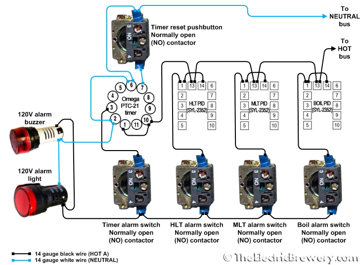
How it works
 While each of the PID controller temperature alarm values is programmed separately, the PID alarm outputs (together with the timer alarm output) are wired in parallel. It only takes one of the 4 devices to sound the alarm.
If any of the PID controllers or the timer raises an alarm state, an internal relay in the device is closed allowing power to flow to the 120V alarm buzzer and 120V alarm light as long as the respective alarm selector switch is also in the ON position.
The 4 alarm on/off selector switches are used to enable/disable the individual device alarms as desired. When all 4 are off, the 120V alarm buzzer will not sound and the 120V alarm light will not turn on.
Using separate alarm on/off switches makes it quick and easy to turn on or off a single alarm without affecting the others, and does not require us to reprogram the individual PIDs or timer alarm settings on every use. It provides the ultimate in flexibility and ease of use.
If using the newer JSL-74A timer it will be set to automatically start counting down as soon as it is powered through the settings (more on this later). If using the original Eagle B506-5001/Omega PTC-21 timer terminals 6 (START) and 2 (NEUTRAL) are shorted and wired to enable this automatic counting down feature.
If you are using a different timer, be aware that it will have different terminal connections and programming steps. You'll need to refer to your timer manual for wiring diagrams and programming instructions.
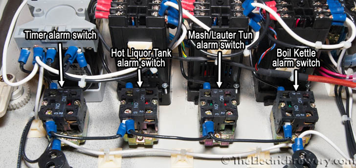
Location of the components:
Close-ups:

STEP 11: Wire up heating elements
 One heating element uses approximately 23 amps of current (out of the 30 amps available in our control panel) so it's important that only one element be active at once. Trying to use two would cause our 30A circuit breaker to trip.
We can't assume that the operator will always turn down the temperature on one PID controller to shut one element off before turning on the other one. No device should be designed such that the power requirements can be exceeded if switches or controls are used in the right (or wrong) order. That would be a poor design just waiting for an accident to happen.
We control which of the two heating elements may be active with the ELEMENT SELECT 3 position switch. It has 3 settings: BOIL, OFF, or HLT. The OFF setting is purposely placed in between the other two to ensure that one element is truly off before the other is turned on. The ELEMENT SELECT switch does not turn on the respective element; it only allows the element to be on if the PID controller/SSR wants it to be on. In other words, the PID controller may be firing the SSR but unless the ELEMENT SELECT switch is also set correctly the element will not receive any power.
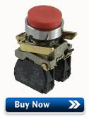
Two ELEMENT ON 220V pilot lights are used to let us know when power is being applied to one of the two heating elements. This is an added safety precaution to show us what is going on.
The ELEMENT SELECT 3 position switch is used to control which (if either) of the two kettles can receive power.
The ELEMENT ON 220V pilot lights show us when a heating element is firing.
Wire up the components as shown in the diagram below using the wire sizes and colours indicated.
Heating element wiring diagram: 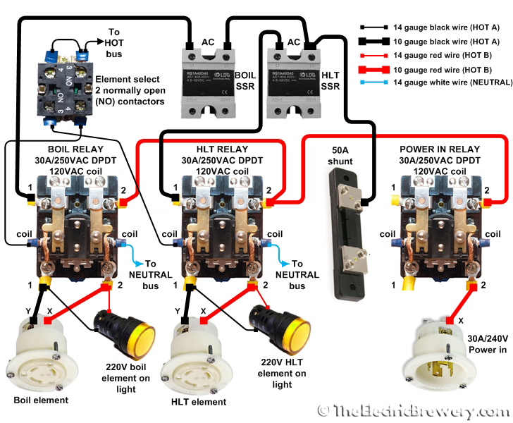
How it works
The Boil Kettle and Hot Liquor Tank heating elements are fed from the 120V HOT A and HOT B lines for a total (differential actually) of 240V.
When the ELEMENT SELECT 3 position switch is turned to either BOIL or HLT, the switch energizes either the BOIL or HLT relay coil which in turn allows power to pass only to that one heating element regardless of how the PID controllers are set. While 120V may be presented to one side of the heating element through the red HOT A line, current will not flow (and therefore heat will not be generated) until the entire loop is closed by the relay and SSR pair.
At first glance the BOIL and HLT relays may seem redundant: We use a PID which controls an SSR which in turn tells the element when to fire. So why are the mechanical relays needed at all? Why don't we simply use the ELEMENT SELECT 3 position switch between the PIDs and SSRs instead? The reason is safety: The mechanical relays ensure that there is a complete physical disconnect between both HOT lines and the heating elements when the relay is off. This is important as we will often be working or cleaning one kettle while the other is operational.
 Doing something similar with SSRs would require 2 SSRs per heating element (one for HOT A and one for HOT B), but even that would not be 100% safe as SSRs have a small amount of leakage current that flows through at all times, even when the SSR is off. SSRs are also known to fail from time to time and when they do, they tend to fail "closed" meaning that the heating element stays on. The mechanical relays provide us with the peace of mind that when we've turned the element off, there is no possibility of it coming on by accident nor is any side of it energized.
So why use SSRs at all? Why can't we just use the mechanical relays? SSRs are Solid State Relays, essentially switches with no moving parts so they are able to switch as fast as required, often many times per second. Regular mechanical relays are not meant for this amount of switching as the contacts would wear out quickly. Whenever frequent switching is required, SSRs are used instead as we've done here. The three 30A/240V DPDT relays we use are only switched once or twice during the brewing session so they are being used in the way that they are designed to operate.
Whenever power flows to one of the heating elements, the respective ELEMENT ON 220V pilot light (wired in parallel with the element) turns on letting us know that power is being applied. This is an added safety precaution to show us what is going on. The PID controller may be firing the SSR, but unless the respective mechanical relay is also on the ELEMENT ON 220V pilot light will not come on.
Location of the components:
Close-ups:


STEP 12: Wall mounting
The control panel is quite heavy once assembled (we'd guess at least 40-50 lbs). How you fasten it to the wall will depend on the material/composition of the wall in your brewery.
If your brewery walls use standard wall studs made out of wood, you'll want to use 4" lag bolts through the tile/drywall to fasten the panel directly to the studs for proper support. If the walls are concrete or cinder block, use 4" concrete bolts.
Four mounting brackets are included with the enclosure for wall mounting. The space between the mounting brackets did not align with the standard wall stud spacing in our brewery so we used a 24x28x3/4" back plate made out of MDF.
The back plate was stained to match the brew stand and then attached to a wall stud in 3 locations using 4x3/8" lag bolts and washers. Prior to permanently attaching the back plate to the wall, 4 holes were drilled and countersunk from the back for the 4 mounting bracket bolts. The control panel was then mounted to the back plate using the included mounting brackets. The bolts come through the back plate from the back such that the nuts are attached from the outside. This allows us to remove the control panel without having to remove the back plate (if required).
1/2" to 3/4" pipe straps were used for cable management. The straps were only attached on one side to make it possible to remove the cables if required.
Mounting bracket holding the control panel to the back plate:


Pipe straps keep the cables organized:
There you have it! Your control panel is now 100% operational!
Continue on to Building Your Brewery - Control Panel (Safe start interlock).
