Control Panel (Safe start interlock)
Introduction
 This is an optional part of the control panel assembly instructions. In this article we'll show you how to add a 'safe start' interlock to your control panel.
If you have not already done so, make sure to visit part 1 and part 2 of the control panel assembly instructions. This article assumes that you've assembled and wired your control panel as outlined in the previous two parts.
An interlock is a device used to prevent a machine from harming its operator or damaging itself. Safe start interlocks are typically found on machinery that may be dangerous. It ensures that the machinery cannot be turned on unless certain conditions are first met. For example, most vehicles can only be started with the gear shift in park.
Adding a safe start interlock to our control panel will avoid harming the pumps, heating elements, and the operator. Whenever using the control panel as built in part 1 and part 2, before it is turned on you must check to make sure that the ELEMENT SELECT and PUMP switches are all in the OFF position. The pumps we use can be damaged if run dry and the heating elements should only be used when submerged in liquid. (While the ULWD elements we use will not break as easily if fired up "dry" like regular elements, it's still best that they be used correctly).
 In addition, from an ergonomic/process control standpoint, when power is cut to the panel (either on purpose or because of a power outage) the pumps and heating elements should not automatically come back on when power is reintroduced (sometimes suddenly).
Our safe start interlock will therefore only allow the control panel to power up if the pump and element switches are all in the OFF position. If any of the three switches is in the ON position, the control panel will refuse to power up: Turning the power key switch will do nothing. This interlock will also ensure that if power is ever cut, the pumps and elements will stay off until the operator turns them off and then resets the power.
This may seem like an unnecessary precaution to some people so you may consider this article as optional. The extra parts required however are inexpensive as the main parts we need to add is an 8-pin relay with 110-120VAC coil and an 8-pin socket. We hope that most people building a control panel like ours will spend the extra effort to put in a safe start interlock. It's quick and easy to do. If you build your control panel exactly like ours, you already have most of the other parts you need.
The 8-pin relay with 110-120VAC coil and 8-pin socket we added to our control panel to provide a safe start interlock: 
Parts and tools
To purchase a control panel pre-assembled or in kit form, see our shop.
The following parts are needed:
-
(Qty: 1) 8-pin relay socket

-
(Qty: 1) 6x2.5" rectangular stainless steel sheet (left over from having purchased the Blichmann BoilerMaker kettle)

-
(Qty: 2) 1/8 x 1" stove bolt and nut

-
(Qty: 5) Self-adhesive tie mount

-
(Qty: 20) Small nylon cable tie


You'll also need the following tools:
-
- or -


*You likely already have extra unused NC contact blocks from the various switches you already purchased.
Some sellers do not ship outside the USA. If you live outside the USA (like us), we recommend using a forwarding service such as Shipito. We've used them to ship to Canada. The good news is that shipping within the USA is very inexpensive or often free. You then simply pay a small forwarded fee plus the cost of whatever shipping method you choose (USPS, FedEx, etc.). They will even consolidate multiple packages into one to save on shipping. We recommend USPS whenever possible to minimize brokerage fees.
Purchasing through our affiliate links helps support our site at no extra cost to you. We thank you!
STEP 1: Install small back plate
This safe start interlock was added after our control panel had already been designed and built. The orange back plate in our control panel enclosure was therefore already full so we had to find a different location to install the 8-pin relay with 110-120VAC coil and 8-pin socket.
We decided to install a new small back plate on the door in the empty spot between the two pump switches.
We cut a 6x2.5" piece off the remaining 6x10" stainless steel shield that shipped with our Blichmann BoilerMaker kettles for this new plate. Hole locations were measured and drilled with a 3/16" high speed metal drill bit using a drill press. Cutting fluid was used when drilling as even thin stainless steel is very hard to drill through.
This plate was attached to the door using the four existing 1/8 x 1/2" stove bolts that hold the 4x2" black aluminum tag in place. The 8-pin relay socket is then bolted to the center of this new back plate using two 1/8 x 1" stove bolts and nuts.
The new small back plate will be located between the two pump switches:
Marking the location of the holes for the new back plate:
New back plate with relay and socket installed:
Close-up of the relay and socket:
STEP 2: Wire up relay
Refer to the wiring basics section of the Control Panel (Part 2) instructions for some hints and tips on how to properly install spade terminals, self-adhesive tie mounts, and nylon ties.
When you previously purchased the various selector switches, they most likely came with both a normally open (NO) and a normally closed (NC) contactor. Up until now we have not used the NC contactors. We will be wiring up the two NC contactors on the pump switches and adding two NC contactors to the ELEMENT SELECT switch. These two new NC contactors are screwed into the backs of the existing NO contactors (see picture further below). Use two of the NC contactors from any of the other switches (other than the pump switches of course).
Wire up the components as shown in the diagram below using the wire sizes and colours indicated.
Some hints:
- White (NEUTRAL) wires are shown as blue in the diagram.
- When orientation is not important, it is not shown. For example, it does not matter which side of NC contactors are wired as they are simply switches and switches do not have polarity.
- The POWER KEY switch was previously wired directly to the POWER IN RELAY coil. This wire must be removed otherwise the interlock feature will be bypassed and the control panel will power up regardless of how the three other switches are set.
- Previously the WORT PUMP and WATER PUMP switches only had their normally open (NO) contactor wired up. We are now adding a normally closed (NC) contactor beside the existing contactor. Only the new wiring is shown here. The existing wiring does not change.
- Previously the ELEMENT SELECT switch contained two normally open (NO) contactor that were wired up. We are now adding two normally closed (NC) contactors on top of the existing contactors. Only the new wiring is shown here. The existing wiring does not change.
Safe start interlock wiring diagram: 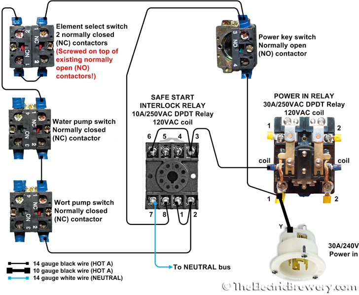
How it works
The safe start interlock relay only receives power when the POWER KEY switch is set to ON and all three other switches are set to OFF. Once the interlock relay receives power and latches, it feeds into the POWER IN RELAY coil to turn on the rest of the control panel. Once latched, power for the interlock relay is then also drawn directly from the POWER KEY switch through one of the poles in the interlock relay that is now closed. This keeps the interlock relay coil energized and allows the other three switches to be turned ON or OFF as required without turning off the control panel while in use or affecting the interlock capability. If power to the panel is cut, the interlock relay releases and the three switches must be set to OFF before the panel may be powered on again.
Our interlock relay has a test LED that will light up when the relay is closed. A red pushbutton on the front of the relay can be used to temporarily switch the relay manually. Neither of these is overly useful in our application, but many relays now include these features.
Location of the components:
Close-up of the relay and pump switches:
The ELEMENT SELECT switch with two NC contactors (right) on top of the existing NO contactors (left):
Done!
To test your new safe start interlock turn the control panel off and unplug the element and pump plugs from the bottom of the control panel (just in case). Set either or both of the pump switches to ON and/or the ELEMENT SELECT switch to BOIL or HLT and then turn on the POWER KEY switch. You'll notice that the control panel does not power up. The pump and element switches must all be set to OFF before the control panel will power up. You'll also note that if you turn off the control panel or lose power when any of the three switches are in the ON position, you will not be able to turn the panel back on until all three switches are first turned OFF.
While not an absolute requirement, this safe start interlock adds a little piece of mind and safety to our control panel for very little effort or cost. Brew safe!
Continue on to Building Your Brewery - Control Panel (Setup).
