Control Panel (Part 1)
- Introduction
- Parts and tools
- STEP 1: Choose enclosure
- STEP 2: Seal cable plate
- STEP 3: Choose heat sink(s)
- STEP 4: Cut holes
- STEP 5: Move grounding post
- STEP 6: Prime and paint
- STEP 7: Install switches
- STEP 8: Install lights and buzzer
- STEP 9: Install Volt/Amp meters
- STEP 10: Install PIDs and timer
- STEP 11: Install receptacles
- STEP 12: Install tags
- STEP 13: Install handles
- STEP 14: Install heat sink/SSRs
Introduction
 Our Standard 30A Electric Brewery Control Panel outlined here is perfect for producing up to 20 gallons of finished product per batch. A single 5500W element is used in both the boil kettle and hot liquor tank.
For alternate control panel builds see:
- Standard 30A Electric Brewery Control Panel (240V only, for international use)
- 50A Electric Brewery Control Panel for back to back batches
- 50A Electric Brewery Control Panel for back to back batches (240V only, for international use)
- 50A Electric Brewery Control Panel for 30+ gallons
- 50A Electric Brewery Control Panel for 30+ gallons (240V only, for international use)
Want to test your panel progressively as you build it? See our Testing Your Control Panel as You Build It guide.
Having problems with a panel you've already built? See our Control Panel Troubleshooting guide.
Control panels are available assembled and in kit form. See our Electric Brewery Control Panels order page.
The control panel houses the lights, switches, and controls that we use to monitor and control our brewing process.
It's a 100% custom unit designed and built by us specifically for our brewing setup using mainly non-proprietary (off-the-shelf) industrial-grade components to ensure long term serviceability. (More information)
The control panel was by far the most complex part of our brewery to design, as just about every part of the brewing process has an impact on the control panel.
All brewing process decisions had to be made prior to designing the control panel to ensure that the panel included the features we needed, worked well ergonomically, and is safe to use.
Once the control panel was designed and parts were chosen, the actual assembly was fairly straight forward.
The control panel houses the lights, switches, and controls that we use to monitor and control our brewing process:
The pumps, temperature probes, and heating elements connect to the underside of the panel. All cables are detachable and feature locking plugs or connectors to avoid accidental disconnection. (Some of the cables are quite heavy).
The pumps and heating elements use female receptacles, while the 30A/240V main power input uses a male receptacle. This is done for safety reasons as it ensures that live AC power will never be available on either the plug or receptacle if something is disconnected by accident.
The temperature probes use female receptacles and are extremely low voltage DC. There is no safety concern if a temperature probe is disconnected during use.
We connect cables to the control panel using plugs, connectors, and receptacles:
All cable receptacles are located underneath the control panel: 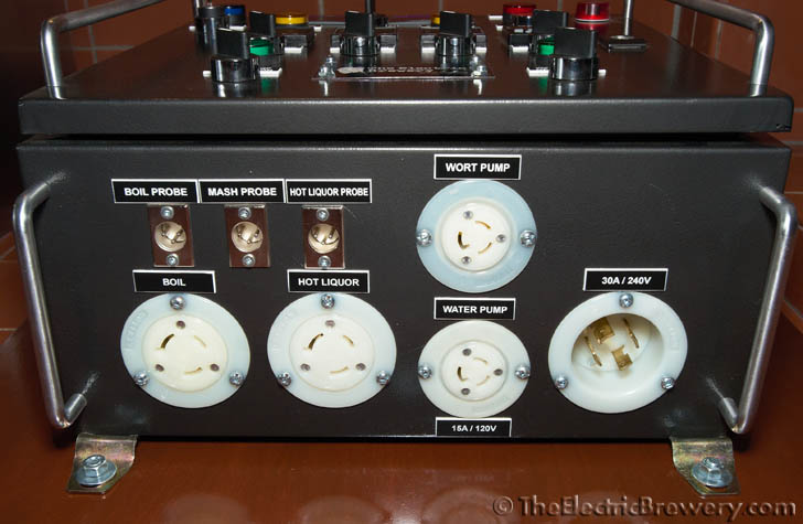

Considerable time was spent designing a layout that is balanced and works ergonomically:
We received assistance from our resident Master Electrician while assembling our control panel:
Instructions for building the control panel are split into multiple articles.
In this first part we'll show you how to prepare the enclosure and install the various external components. In the second part we'll install the internal components and provide wiring details. A last (optional) part provides details on adding a safe start interlock for safety.
Parts and tools
To purchase control panels pre-assembled or in kit form, see our order page.
The following parts are needed:
- (Qty: 1) 16x16x8" watertight steel box enclosure with a locking door
- (Qty: 1) Large heat sink (see text)
- (Qty: 2) 40 amp SSR (12VDC input voltage, 240VAC output voltage)
- (Qty: 3) SYL-2352 PID temperature controller, 1/16 DIN size, SSR output, 85-264VAC supply
- (Qty: 1) RECOMMENDED: JSL-74A multi-programmable LED timer, 1/16 DIN size, 90-260VAC supply
- or -
(Qty: 1) Eagle B506-5001/Omega PTC-21 multi-programmable LED timer with socket, 1/16 DIN size, 90-264VAC supply - (Qty: 1) 3 digit blue LED digital panel volt meter 700V AC, 5V DC supply
- (Qty: 1) 3 digit blue LED digital panel amp meter 50 amp AC with shunt, 5V DC supply
- (Qty: 1) Blue 22mm LED pilot light, 100-120V AC/DC
- (Qty: 1) Red 22mm LED pilot light, 100-120V AC/DC
- (Qty: 2) Green 22mm LED pilot light, 100-120V AC/DC
- (Qty: 2) Yellow 22mm LED pilot light, 220V-240V AC/DC
- (Qty: 1) Buzzer, 22mm, 110-120V AC/DC
- (Qty: 6) 2 position maintained selector switch, 1 normally open (NO) contactor, 10A/240VAC
- (Qty: 1) 2 position maintained selector switch with key, 1 normally open (NO) contactor, 10A/240VAC
- (Qty: 1) 3 position maintained selector switch, 2 normally open (NO) contactors, 10A/240VAC
- (Qty: 1) Red pushbutton, 22mm, momentary, 1 normally open (NO) contactor, 10A/240VAC
- (Qty: 3) XLR chassis mount male receptacle, 3 pin
- (Qty: 2) NEMA L6-30 (250VAC, 30A) twist lock electrical female receptacle
- (Qty: 2) NEMA L5-15 (125VAC, 15A) twist lock electrical female receptacle
- (Qty: 1) NEMA L14-30 (125/250VAC, 30A) twist lock electrical male receptacle
- (Qty: 1) 8-32 x 1" stove bolt and nut*
- (Qty: 6) #4 x 1" wood/metal screw
- (Qty: 10) #6-32 x 1/2" machine screw
- (Qty: 6) #6-32 hex nut
- (Qty: 13) 3/16 x 1/2" stove bolt and nut
- (Qty: 4) 1/8 x 1/2" stove bolt
- (Qty: 4) 1/8" Stainless steel acorn cap nut
- (Qty: 6) 1/4-20 x 1" stove bolt
- (Qty: 1) Aerosol spray can of general purpose grey enamel primer (for priming metal)*
- (Qty: 1) Aerosol spray can of hammered metal finish spray paint - charcoal colour (for painting metal)*
- (Qty: 2) 305mm (12") handle
- (Qty: 4) 127mm (5") handle
- (Qty: 1) Tube of all purpose clear silicone sealant
- (Qty: 1) JB Weld cold weld compound*
- (1 tube) Heat sink compound
- (Qty: 27) 1-3/4 x 1/2" custom electrical panel tags (see text)
- (Qty: 1) 4 x 2" black aluminum tag with name/logo (see text)
You'll also need the following tools:
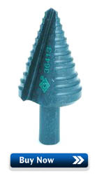
- GreenLee 36414 1-3/8" step drill bit***
- GreenLee 1/2" conduit punch for making 7/8" (22mm) diameter holes***
- ~45mm (1-3/4") bi-metal hole saw for making ~45mm (1-3/4") diameter holes**/***
- ~51mm (2") bi-metal hole saw for making ~51mm (2") diameter holes**/***
- ~57mm (2-1/4") bi-metal hole saw for making ~57mm (2-1/4") diameter holes**/***
- Hand drill***
- Drill press***
- High speed steel (HSS) drill bits***
- Jigsaw***
- Jigsaw blades for cutting metal***
- Cutting fluid***
- Metal file***
- Hacksaw
- Tap and die set***
- Screwdrivers
- Sharpie permanent marker***
- Masking tape*
- Sandpaper*
*Not required if building from one of our control panel kits. Our kit enclosures are custom made for us and result in less work for you. There is no need to move the ground post, no need to seal and sand the bottom cable plate, and no need to prime and paint as the enclosure is already professionally powder coated with an industrial flat textured charcoal/black finish.
**WARNING: The hole sizes will vary slightly based on the receptacle brand used. Before cutting, confirm the hole sizes required by measuring the actual receptacles you will be installing.
***Not required if you are building from one of our control panel kits and you opted to have the enclosure pre-punched.
Some sellers do not ship outside the USA. If you live outside the USA (like us), we recommend using a forwarding service such as Shipito. We've used them to ship to Canada. The good news is that shipping within the USA is very inexpensive or often free. You then simply pay a small forwarded fee plus the cost of whatever shipping method you choose (USPS, FedEx, etc.). They will even consolidate multiple packages into one to save on shipping. We recommend USPS whenever possible to minimize brokerage fees.
Purchasing through our affiliate links helps support our site at no extra cost to you. We thank you!
STEP 1: Choose enclosure
 We use a 16x16x8" watertight steel box enclosure with a locking door to house our control panel components.
A larger enclosure may also be used, such as 20x16x8" or 20x20x8". There's no such thing as too much space. Don't go any smaller however as space will be tight.
This enclosure is rated to the following NEMA and IP protection standards:
- NEMA 4: Watertight (weatherproof). Must exclude at least 65 GPM of water from 1-in. nozzle delivered from a distance not less than 10 ft for 5 min. Used outdoors on ship docks, in dairies, and in breweries.
- NEMA 12: General-purpose. Intended for indoor use, provides some protection against dust, falling dirt, and dripping noncorrosive liquids. Meets drip, dust, and rust resistance tests.
- IP65: No ingress of dust; complete protection against contact. Water projected by a nozzle against enclosure from any direction shall have no harmful effects (i.e.: can be used in washdown conditions).
It's important to note that these ratings are only for the enclosure itself. Once you punch a hole in it to add a component, to maintain the rating the component that's been added must also be rated to the same protection standards and be mounted correctly.
To meet watertight ratings the accessible parts must present some sort of barrier and use a gasket to create a seal with the enclosure.
Most of the components we use are rated to provide adequate water and moisture protection in our brewery. While we don't intentionally get the panel wet, having some protection helps against accidents.
 Protection ratings and what they mean for home use: In most locations you do not actually need to build your control panel to specific ratings when only used in the home. The ratings are only required for commercial settings that have to undergo regular inspections as they are required to have safe workplaces for their employees. In most locations, you, the homeowner can build and use anything you like as long as it is not permanently connected to the rest of your house. That does not mean however that it will be safe for you to use (only you can be the judge of that). We feel that anything you build for home use should still be built to be safe to use so we try to follow industry standards as much as possible.
All purpose clear silicone sealant was used on the inside of the enclosure around some of the unrated components (Amp/Volt meters and receptacles) to better seal them against outside elements.
The cord plugs and connectors that plug into the control panel are not, however, watertight. Weather-resistant sealing rubber boots would have to be used if complete protection against moisture is required for the cords. We didn't feel this was necessary for a panel used primarily indoors.
Indoor/outdoor rated 16x16x8" steel box enclosure. The reversible hinges allow for 120 degree door opening.
The orange back plate is removable for easy mounting of internal components. Four wall mounting brackets are included.
A polyurethane gasket and front rain gutter ensure a high degree of protection. The ground wire ensures that the door is properly grounded to the rest of the chassis.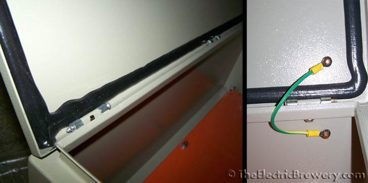
A removable handle is used to lock the door.
STEP 2: Seal cable plate
 You may skip this step if building from one of our control panel kits as the custom enclosure we include does not have a cable plate.
The removable cable plate is normally positioned on the bottom of the enclosure to house cable receptacles and other attachments to outside devices.
This plate is too small for all the receptacles we need to use so we epoxied it permanently to the enclosure using JB Weld cold weld compound. The cable plate also comes with a gasket to ensure a water tight seal. This is not needed since we're going to bond it permanently to the rest of the enclosure.
The enclosure was then oriented such that the plate is at the top (under the large heat sink).
The receptacles were installed on the opposite (bottom) side.
Removable cable plate:
Seal the removable cable tray using JB Weld. We wanted a flat surface so only the cable tray screws were used (not the nuts).
Use masking tape to the hold cable tray screws in place from underneath. This provides a place for the JB Weld to pool. Apply JB Weld around each screw end as shown below. Let dry overnight and then file down the screws ends and sand until the surface is flat.
The result should be a nearly flat surface ready for our heat sink.
Cable plate epoxied to the enclosure using JB Weld:
STEP 3: Choose heat sink(s)
 Large black anodized heat sinks are nearly impossible to find at reasonable prices. To make life easier for those who wish to build their own control panel, we've partnered with a manufacturer to purchase large aluminum heat sinks in volume and then professionally anodize them in batches to reduce the cost. It is also included in our control panel kits. See our heat sink order page.
The size and position of the holes you create on the top of the control panel depend on the heat sink(s) you use. We need to make that choice now before continuing.
Inside the control panel are two SSRs (solid state relays) that are used to turn the heating elements on and off. An SSR creates a lot of heat and requires a heat sink to dissipate this heat otherwise it will overheat and burn out quickly.
SSRs are sold by the amperage that they are able to switch. Popular sizes include 10, 25, 40, 80, and 100 amps. Heat sinks are often sold bundled with SSRs to match their size. The more current that is switched, the larger the heat sink required.
Our 5500W elements consume approximately 23 amps of current when in use, requiring at least a 25 amp SSR. This is, however, very close the maximum rating of the SSR so we chose instead to use a 40 amp SSR and run it at around half the rated capacity. Like most electronic and mechanical devices, an SSR will last longer if it's not driven to the top end of its rated capacity.
 Using a heat sink that is typically sold with a 40 amp SSR should be more than adequate since we are only switching 23 amps. The heat sink will provide better cooling to offset situations like poor air flow or warm ambient temperatures since it is oversized.
Of course, if a 40 amp heat sink cools better than a 25 amp, why not go even larger? The larger the heat sink, the better the cooling and the less stress on the SSRs. After many months of searching we found an even larger used heat sink for sale on eBay so we use it to cool both SSRs instead. It does not even get warm to the touch.
Our heat sink is 12" wide, 7" deep, and 3" high. It is most certainly overkill for this situation. Assuming the fin density between the standard 40 amp heat sink and our 'overkill' heat sink are the same, ours is 4.2 times larger (252 cubic inches versus 2 x 30 cubic inches).
If you decide to source your own large heat sink, keep it between 8-13" long and 4-7" deep. Anything larger will not fit properly on top of the enclosure and leave enough room to use the carrying handles. Height is not overly important. Any heat sink this large over 1-2" high will certainly cool adequately. An anodized aluminum heat sink will cool better than a non-anodized (silver) heat sink. (More information)
Using two standard 40 amp heat sinks meant for 40A SSRs is certainly more than adequate but they may be harder to mount outside the enclosure as many present a surface area only large enough for the SSR, leaving no room for mounting to the enclosure. If you'd like to use a larger heat sink as we did, by all means go for it but do not feel it's a requirement. We just preferred the increased cooling ability and the look of one large heat sink compared to two smaller ones.
Our 'overkill' heat sink (for two SSRs) next to a standard 40 amp heat sink (meant for a single SSR):
The 10" x 5.375" x 1.375" custom heat sink sold through our products page is perfectly suited for our control panel. The low profile means that the fins are exactly the same height as the handles we will be installing later. A perfect match!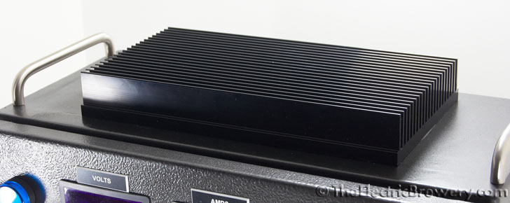
STEP 4: Cut holes
You may skip this step if building from one of our control panel kits and you opted to have the enclosure pre-punched as we will already have done this work for you.
We need to cut holes on the door, top, and bottom of the enclosure to attach the various controls and other parts.
 Most industrial components come in various standardized sizes. This makes it much easier to replace components (if required) as you won't need a whole new enclosure if the replacement component comes from a different manufacturer. Everyone uses the same size cutouts.
Standard industrial controls sizes (for whatever reason) are always indicated in metric units, usually millimetres (mm). For this reason you'll find that we often mix imperial and metric units (such as inches and millimetres) as we want to stick with the standard terms that are used in industry whenever possible when describing controls. For example, people will talk about a "22mm switch", not a "0.86614 inch switch".
With the exception of the Amp and Volt meters, everything on our control panel uses standardized sizes. Our PID controllers and timer are DIN 1/16 size which requires a 45x45mm panel cutout. The Amp and Volt meters require a 71x39mm cutout (non-standard sizing).
To create the square and rectangular holes required for these devices, use a hand drill or drill press with a high speed steel (HSS) drill bit to first drill holes in the corners and then cut between the holes using a jigsaw with a fine metal blade. Use a metal file to smooth down all rough edges and corners.
DIN 1/16 punches are available too and are much easier to use, but expect to pay an arm and leg for them. They typically cost over $500 which works out to $125 per hole! At that price we'd rather just use a little more elbow grease to get the job done.
DIN sizes (from left to right): 1/4, 1/8, 1/16, and 1/32. We use the DIN 1/16 size for our PID controllers and timer.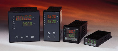
For industrial switches, pushbuttons, and indicator lights, the most common sizes are 22mm and 30mm. This size represents the panel hole diameter required.
22mm devices cost less and require less space. 30mm devices are regularly seen in heavier industrial settings where the panels are often used by gloved workers so buttons and switches need to be larger. 30mm devices are generally more durable and made to withstand abuse and are, therefore, more expensive.
 For our small panel with controls that are rarely used (relatively speaking), 22mm devices are adequate. The smaller size also suits the other components: 30mm switches and lights would have appeared oddly large next to the small Amp/Volt meters and PID controllers.
You have two options for making these holes:
- RECOMMENDED: Use a GreenLee 1/2" conduit punch to punch out the 22mm diameter hole. (A 1/2" conduit punch actually makes a 7/8" or 22mm hole). This is the recommended method (especially if you do not have a drill press) as it results in a clean and perfectly centered hole with the least amount of work. Refer to Step 4: Punch a hole in the kettle from the Heating Elements section for instructions on how to properly create clean holes using a punch like this.
- Use a GreenLee 36414 1-3/8" step drill bit (avoid cheap knockoffs!) to drill the entire 22mm hole. Make sure to stop when you reach a diameter of 22mm (0.867"). Go slowly and use cutting fluid to avoid overheating the step bit. While a hand drill will work, a drill press makes work considerably easier and more precise as it keeps the step bit from pulling in one direction which can result in holes that are not perfectly aligned. Use a metal file to smooth down any rough edges.
The location and size of the holes are shown in the pictures below. For example, the hole for the blue power light at the top left is centered 2" from the top edge and 1-1/2" from the left edge of the panel.
Use a metal file to create the little notches on the sides of the holes for the Amp and Volt meters (as shown the photos below) to help make insertion easier.
Front door hole location and sizes:
Use a GreenLee 36414 1-3/8" step drill bit to drill the 22m diameter holes. Make sure to apply cutting fluid as you proceed to avoid overheating the bit.
The temperature probe, heating element, pump, and the main power input receptacle holes will vary in size based on the receptacles you use.
We used a GreenLee 36414 1-3/8" step drill bit to drill ~18mm* diameter holes for the XLR receptacles and then bi-metal hole saws to cut ~45mm*, ~51mm*, and ~57mm* holes.
*WARNING! The hole sizes will vary slightly based on the receptacle brand used. Before cutting, confirm the hole sizes required by measuring the actual receptacles you will be installing.
Insert the receptacles temporarily to mark the locations of the screw holes with a sharpie permanent marker and then drill using high speed steel (HSS) drill bits.
Cutting the receptacle holes:
The size and position of the hole(s) on top of the enclosure depends on the size and number of heat sinks (one or two) that are used. This choice was made earlier.
We use one large heat sink on the top of our control panel so one 7 x 2-1/2" hole was cut. If you chose to use two standard 40 amp heat sinks, two 1-3/4 x 2-1/4" holes are required instead.
To create the rectangular holes use a drill with a high speed steel (HSS) drill bit to first drill holes in the corners and then cut between the holes using a jigsaw with a fine metal blade. Use a metal file to smooth down all rough edges and corners.
The hole on top for our large heat sink is 7 x 2-1/2" and centered: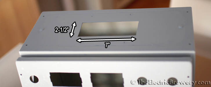
If using two standard 40 amp SSR heat sinks, cut two holes that are 1-3/4 x 2-1/4" in size instead. Center the holes on the top of the enclosure and leave a few inches between them to provide better air circulation around the heat sinks.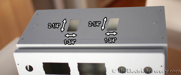
During the design phase of our brewing setup we wanted to keep our options open and therefore cut a hole large enough to accommodate a third SSR. A third SSR would have been required if we had chosen to go with a RIMS (Recirculating Infusion Mash System) setup instead of a HERMS (Heat Exchanged Recirculating Mash System) setup (more information).
Inside of the control panel showing the two SSRs attached to the external heat sink:
STEP 5: Move grounding post
 You may skip this step if building from one of our control panel kits as the grounding post in the custom enclosure we include does not need to be moved.
The enclosure door includes a grounding post that (as luck would have it) will be in the way of our blue LED power light. We're going to move the post.
Cut the post off and file the stump down on the inside of the door until reasonably flat. Drill a small 1/8" diameter hole using a bit approximately half way between the blue LED power light and volt meter holes using drill and a high speed steel (HSS) drill bit. Sand off the paint around the hole on the inside of the door and install a 8-32 x 1" stove bolt such that the bolt head is on the outside of the door. Use a nut on the inside and tighten down firmly. The nut pressing against the bare metal door ensures that the stove bolt makes good electrical contact with the door. The stove bolt and door are now 'connected' electrically.
Apply liberal amounts of JB Weld epoxy at the base of the stove bolt on the inside of the door. Use enough so that it completely covers the nut and some of the door (see picture below). Allow to dry overnight and apply a second layer of JB Weld if required and wait. File down the head of the stove bolt on the outside until flush with the door panel. Done! The grounding post has been moved. Once we prime and paint the door it won't be obvious that the grounding post was moved.
The grounding post was moved to make room for the blue LED power light:
STEP 6: Prime and paint
 You may skip this step if building from one of our control panel kits as the custom enclosure we include has already been professionally powder coated with an industrial flat textured charcoal/black finish.
The enclosure as shipped comes both internally and externally protected with polyester epoxy resin texturized grey paint (RAL-7032). It may be protected but it's pretty boring to look at. Time to spruce it up a bit!
File down any rough edges and lightly sand the outside of the enclosure.
We primed with Tremclad primer and then painted the enclosure with Tremclad Rust-Oleum charcoal coloured hammered metal finish spray paint to give the box a metallic look. Feel free to use any colour you like of course.
This spray paint is intended for use on outdoor equipment and furniture so it's tough and built to take abuse.
This is the same type (but different colour) spray paint we used on our heating element boxes.
Tremclad general purpose grey enamel primer and charcoal Rust-Oleum hammered metal finish spray paint:
Enclosure primed:
The metal parts of the lock mechanism were taped up and the plastic parts primed as well: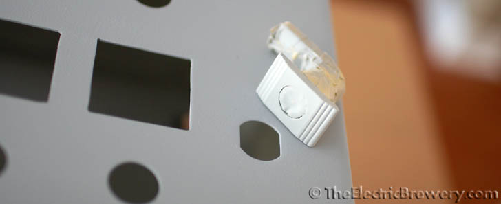
The special Tremclad Rust-Oleum hammered metal finish gives the control panel a metallic look that is very durable:
Enclosure painted and ready for parts:
Time to mount the external components to the enclosure! This includes all the parts that install to the panel door such as the switches, lights, meters, PID controllers, and so on. On the bottom of the enclosure we install our receptacles.
STEP 7: Install switches
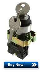 Three types of industrial switches are used on the control panel: Pushbutton switches, selector switches, and key selector switches.
The protection rating of the switches we use is unknown but is likely IP65 or IP54 at the very least, both of which are more than adequate for our brewery usage.
Industrial switches are different from most other switches so some explanation is in order.
The exposed part of the switch that the user pushes or turns is called the 'operator' or 'selector'. Operators can be 'maintained' or 'momentary'. A 'momentary' operator will spring back when it is let go while a 'maintained' operator will stay in position. All of the selector and key selector switches in our control panel have 'maintained' operators while the single pushbutton switch we use has a 'momentary' operator.
When the operator is actioned, it activates the contact block(s) on the inside of the control panel. Contact blocks are simple on/off switches that come in either 'normally open' (NO) or 'normally closed' (NC) varieties. There's typically room for two contact blocks to be screwed directly to the body and additional contact blocks can be piggybacked off those two in any combination as required.
While most of our switches and pushbuttons came with both a NO and NC contact block, we almost exclusively use the NO in our setup. The exception is the 3-way switch labelled 'ELEMENT SELECT' used to switch between heating in the Boil Kettle and Hot Liquor Tank, it uses two NO contact blocks.
Pushbutton, selector, and key selector switches:
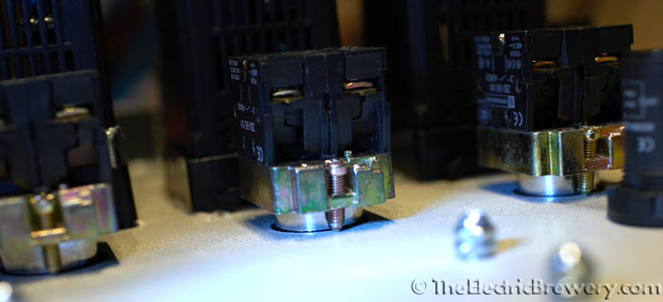
To mount the switches, loosen the two mounting screws and then turn the operator a quarter turn to pull it free from the metal body. Some switches (most notably pushbuttons like the one above) may have a little L-shaped tab you have to pull out slightly first. Do not force the switches apart. They all come apart easily.
Once the operator and body are separated, place the operator through the hole in the door (making sure that the rubber gasket is on the outside of the door), click and turn it in the metal body, and then tighten the mounting screws with a screwdriver until the assembly is held tightly against the door. Even though the body on some models may be metal, do not overtighten or you may crack it. If the body does not shift or turn when the operator is actioned, it's tight enough.
We tried a few different types of switches before settling on these ones with metal bodies. Some of the all plastic ones we tried simply did not seem like they would last - even the contact blocks used really cheap parts and did not always switch properly.
Close-ups of switches mounted on the door: 

STEP 8: Install lights and buzzer

Pilot lights of various colours are used: Blue for power, red for alarm, yellow for 'element on', and green for 'pump on'.
The lights are all LED pilot lights. The blue, red, and green are 100-120V AC while the yellow are 220-240V AC.
The LED lights we use are brighter and more evenly lit than the incandescent versions we tried and will last considerably longer, not to mention use less power.
The lights conform to the IP65 rating which means they are completely sealed from dust and can withstand water jets.
The 115V AC buzzer emits an annoying piercing shriek, loud enough to wake up just about any brewer after a long brew day.
To mount the lights and buzzer remove the plastic nut, push the light/buzzer through the panel hole (making sure that the rubber gasket is on the outside of the door), and then screw the plastic nut in place from the inside. Finger tight is fine. Do not use tools as you may crack the plastic.
22mm LED pilot lights and buzzer: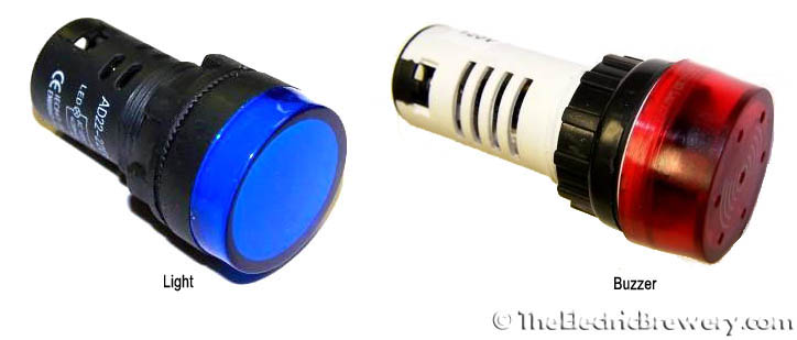
STEP 9: Install Volt/Amp meters
 The amp and volt meters are used to display the AC voltage being fed to the panel and the current consumption.
Neither are truly required for the brewing operation. They simply give us piece of mind that things are operating as expected.
The meters have side tabs that are used to snap them into place.
To ensure a better seal from the outside (the protection rating is unknown), apply a bead of all purpose kitchen/bath silicone sealant around all sides of the meter on the inside of the control panel after snapping them in place.
The amp meter requires a 50 amp shunt which is typically sold with the meter as the two are matched for use together. We'll be installing the shunt in part 2 of the control panel instructions.
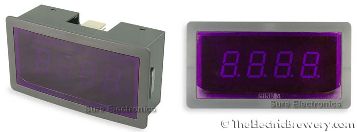
Volt meter installed and caulked with silicone sealant:
STEP 10: Install PIDs and timer
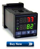 Three SYL-2352 PID controllers are used to display and control the liquid temperatures in our setup.
At approximately $50 each, these are some of the least expensive PID controllers available on the market today. Most industrial PIDs start at $200 and go up from there.
The front panel of the PID controller conforms to an IP54 rating which means it is protected from dust and splashing of water. Not quite as rigid as IP65 (completely sealed from dust and water jets) but still adequate for our usage.
They are 1/16 DIN size (45x45mm).

 An Eagle B506-5001/Omega PTC-21 countdown timer was originally used to time the various brewing steps. It is also 1/16 DIN size (45x45mm) and IP65 rated. The Eagle and Omega timers are identical and only differ in branding. Identical functionality, no wiring changes required. As of 2025 both timers are discontinued so today we recommend the newer JSL-74A timer. It has identical features and also matches our PID controllers.
While other timers will also work, we originally chose the Eagle B506-5001/Omega PTC-21 countdown timer as it has four buttons for changing the time instead of two as found on most other models. You simply press any of the four buttons to change the four digits directly. On models with two buttons change the time is a bit slower.
If power to the control panel is interrupted during a countdown, the Eagle B506-5001/Omega PTC-21 and JSL-74A timer both remember the time and continue where it left off when power returns. This is a very handy feature if you live in an area with frequent power interruptions or happen to turn the control panel off momentarily during use (either on purpose or by accident). Most other timers do not have this non-volatile memory and lose their countdown if power is momentarily lost.
If you choose to use a different timer keep in mind that it will have completely different terminal connections and programming steps as compared to those in this guide. You'll need to refer to your timer manual for wiring diagrams and programming instructions. We offer wiring diagrams and programming instructions for both the original Eagle B506-5001/Omega PTC-21 countdown timer and the newer JSL-74A timer later in our guide.
To install the PID controllers and timer, remove the collar and slide the device through the opening. Slide the collar back on from the inside.
If your PIDs do not include rubber gaskets, before tightening the collar on the PID controllers apply a bead of all purpose kitchen/bath silicone sealant around the edge on the inside of the control panel to provide a better seal. Two #4 x 1" long wood/metal screws were used for each device to hold it in place more securely than just using the plastic collars alone. The collar already comes pre-drilled with holes in opposite corners specifically for this purpose. The Omega PTC-21 collar already includes screws and does not require sealant as it includes a rubber gasket.
PID controllers installed with Silicone sealant around the edge. Two #4 x 1" wood/metal screws help hold the PID tightly against the door.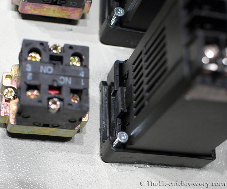
Door components have all been installed. The (original) Eagle B506-5001/Omega PTC-21 timer with large grey socket is seen to the left of the three PID controllers.

STEP 11: Install receptacles
Four types of receptacles are used on the bottom of the enclosure to attach our various cables:
- Three XLR chassis mount male receptacles for the temperature probes
- Two NEMA L6-30 (250VAC, 30A) twist lock electrical female receptacles for the elements
- Two NEMA L5-15 (125VAC, 15A) twist lock electrical female receptacles for the pumps
- One NEMA L14-30 (125/250VAC, 30A) twist lock electrical male receptacle for the power input to the control panel
The small silver temperature probe XLR receptacles are each held in place with two size 6-32 x 1/2" machine screws and 6-32 nuts.
Depending on the style of the AC receptacles, you may find it difficult to tighten the screws that hold the wires in later steps. You may wish to hold off on installing the stove bolts/nuts and applying the silicone until after the AC receptacle wiring is done.
The larger white AC power receptacles are held in place with 3/16 x 1/2" stove bolts and nuts. The 240V receptacles use three bolts each and the pump receptacles use two bolts each.
After installing, apply a bead of all purpose kitchen/bath silicone sealant on the inside of the enclosure where the receptacles meet the enclosure.
Cable receptacles (ignore the wiring - this comes later):
Close-up of the XLR receptacles:
Receptacles partially installed:
The observant reader will note that we actually used NEMA L9-30 receptacles (rated 600 VAC instead of 250 VAC) as these higher voltage plugs were more readily available at the time we assembled our brewery. You may always use a plug or connector rated higher in voltage or current than required - just make sure that your plugs and receptacles match.
STEP 12: Install tags
Electrical panel tags were used to label the various parts of our control panel. It is an inexpensive way to helps give the panel a finished professional look and also makes it safer to use. Before flicking a switch the labels are a confirmation that we're actually going to turn on the pump or element that we expect.
When properly tagged, controls or indicators should be self-describing. What this means is that it should be obvious to the user what the switch or control will do without having to ask, refer to a manual, or simply try it out. For example, for the switches we do this by using two lines of text on the tags: One line to describe what the switch controls (ex: "WATER PUMP") followed by a second line describing what each of the switch positions does (ex: "OFF - ON"). The end result is a panel that anyone slightly familiar with the brewing process should be able to look at and understand without having to ask any questions.
All of the tags have a black face with white lettering, Arial upper case center aligned text, adhesive backing, bevelled edges, no holes, and are 1-3/4 x 1/2" in size.
There are 27 tags in total with the following text:
- VOLTS
- AMPS
- ALARM
- POWER
OFF - ON - ELEMENT ON
- ELEMENT SELECT
BOIL - OFF - HLT - ELEMENT ON
- RESET
- BOIL TEMP
- MASH TEMP
- HOT LIQUOR TEMP
- TIME REMAINING
- ALARM
OFF - ON - ALARM
OFF - ON - ALARM
OFF - ON - ALARM
OFF - ON - WORT PUMP
OFF - ON - WATER PUMP
OFF - ON - BOIL PROBE
- MASH PROBE
- HOT LIQUOR PROBE
- BOIL
- HOT LIQUOR
- WORT PUMP
- WATER PUMP
- 15A/120V
- 30A/240V
A 4x2" black aluminum tag with our Electric Brewery name and logo fills in the empty space at the bottom center of the control panel. 1/8 x 1/2" stove bolts and matching stainless steel cap nuts hold the nametag in place and give it an industrial look that matches our Blichmann kettles.
Below are links to download the original logo in Photoshop and JPG image formats (if you wish to use it) so that you may change the year and location to suit your own brewery:
- TheElectricBrewery.com logo in original Photoshop .PSD format (1200x600 pixel, 287K)
- TheElectricBrewery.com logo in .JPG format (1200x600 pixel, 126K)
Feel free to create your own too of course!
Electrical tags give the control panel a finished professional look and also make it safer and easier to use:
4x2" black aluminum tag with our brewery name and logo:
We went through a bunch of different logos before settling on the one used today:![]()
STEP 13: Install the handles
You may skip the drilling portion of this step if building from one of our control panel kits and you opted to have the enclosure pre-punched as we will already have done this work for you.
 Handles are installed on the top, front, and bottom of the control panel. The handles make carrying easier and also protect the various controls from accidental damage.
The control panel is heavy enough that if it was to fall over on its front it's likely that some of the controls would be damaged. The handles were carefully chosen to be higher than the switches, lights, and buttons installed on the door: The handles are 1-3/8" high while the controls are at most 1" high.
The height of the handles used on the top of the control panel exactly matches the height of the custom heat sinks we offer on our products page.
The handles are usually sold in pairs. Two lengths were used:
Screws are included in the handle kits. You will need to cut the screws down to approximately 1/2" in length with a hacksaw since they're meant for installation through a thicker kitchen cabinet, not a thin metal box.
Use a drill with a high speed steel (HSS) drill bit to create holes in the enclosure and install the handles. Be careful to not damage the polyurethane gasket on the door.

Handles installed on the front and bottom. The handles are 1/4" higher than the door controls which helps protect them.
Careful when installing the door handles to not damage the polyurethane gasket:
Step 14: Install heat sink/SSRs
You may skip the tapping portion of this step if building from one of our control panel kits as we will already have done this work for you.
In an earlier step you chose whether to install one large heat sink or two smaller 40 amp heat sinks. One or two holes were then cut at the top of the enclosure.
Now we're going to mount the SSRs on the heat sink(s) and then install the heat sink(s) on the enclosure.
Exact measurements will not be possible here as it depends on the heat sink you are using. Instead, we'll show you pictures and instructions based on the large heat sink we used.
 Our large heat sink did not come with any threaded holes for screws so we had to create our own. To do this a tap and die set is required. Inexpensive sets are available for $20-30 USD.
Taps are used for adding threads to holes so that screws can be attached. Taps look like funny drill bits with threads on them (see picture to the left). A die is used for adding threads to metal rods to create screws. Dies look like large nuts with threads in the middle. Taps and dies are typically sold in sets. We'll only be using the tap portion of the set since we only need to create threaded holes. No need to make screws. We can simply buy them!
The SSRs are attached to our large heat sink using two 6-32 x 1/2" machine screws while the heat sink itself is attached to the enclosure using six 1/4-20 x 1" stove bolts. The screw sizes aren't overly important. Use whatever you have handy.
If you chose to go with two 40 amp heat sinks, they already include threaded holes for the SSRs as well as the screws. Two other holes will have to be created however to attach the heat sinks to the enclosure.
Drill a pilot hole first using a drill and high speed steel (HSS) drill bit. Refer to your tap and die set for the correct size pilot hole for the screw size you'll be using. Clean all metal shavings out of the holes and then thread the holes using the correct size tap. Go slowly, turning the tap by hand and let the tap do the work.
The top of the enclosure where the heat sink will be installed.
A pilot hole is first drilled in the heat sink and then threaded using a tap (shown below):
 When the SSR heats up during use, the heat sink will 'wick' away heat. To ensure that the contact between the SSR and the heat sink is as perfect as possible with as little to no air as possible (air is a very good insulator) we use a thick white paste called heat sink compound to fill in any small gaps or imperfections between the two surfaces. Heat sink compound is much better at conducting heat than air, allowing a maximum amount of heat to pass from the SSR to the heat sink.
Apply a very thin layer of heat sink compound to the entire surface of the metal plate on the bottom of the SSR. Use just enough to fill in any possible gaps. Press the two surfaces together tightly and then separate to see if the entire area is covered. If not, apply slightly more and repeat.
Screw the SSR tightly to the heat sink.
Note: Don't worry about the quality or brand of heat sink compound used here. For our use there's little difference.
Apply a thin layer of heat sink compound to the bottom of the SSR and press firmly against the heat sink to ensure complete coverage:
Apply a thin bead of all purpose kitchen/bath silicone sealant around the outside bottom of the heat sink. This will ensure that we create a watertight seal with the outside once it is installed. The GE Silicone I product we use (shown in the picture below) is rated to 400F.
Silicone sealant is used for a watertight seal:
Attach the heat sink to the enclosure using six 1/4-20 x 1" stove bolts:
The large heat sink installed, leaving enough room to carry the control panel by the handles:

Your control panel now looks finished! Unfortunately not much happens when you turn the key to power it up...
Move on now to Building Your Brewery - Control Panel (Part 2) where we'll describe how to install the internal components and provide wiring details.
