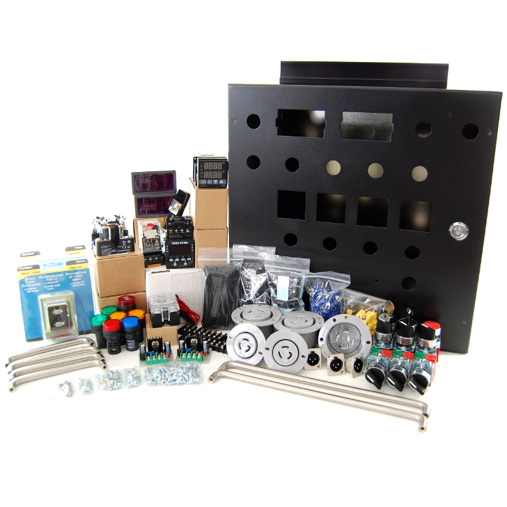
Standard 30A Electric Brewery Control Panel (240V only, for international use)
This control panel is available in kit form through our shop.
These wiring instructions are for our Standard 30A Electric Brewery Control Panel for countries where the mains power is 220-240V only (120V is not available) such as Europe, Asia, Australia, and New Zealand.
Need more power or something custom? Our panels can be interlocked with optional modular booster panels to increase capacity as you grow. Contact us for details.


FAQ
Why are these changes needed? I thought the heating elements ran at 240V even in North America?
Countries with 120V power have the following power connections available:
- GROUND
- NEUTRAL
- HOT A 120V
- HOT B 120V
While the heating elements run at 240V, many of the components in our control panel (PIDs, timer, buzzer, doorbell transformers, relays, and most lights) run at 120V by using the NEUTRAL line together with one of the two HOT lines. The heating elements run at 240V by using both HOT lines together.
Countries with 220-240V power have the following power connections available:
- GROUND (sometimes called EARTH)
- NEUTRAL
- HOT 220-240V (sometimes called LIVE or ACTIVE)
120V is not possible so all components must run at 220-240V. This means that the buzzer, doorbell transformers, relays, and most lights must be replaced with 220-240V versions. The PIDs and timer continue to work as they work anywhere from 90 to 264V.
Wiring changes are required as there is only one 220-240V HOT line instead of two 120V HOT lines.
Does it matter if the power is 50 or 60Hz?
No. The frequency of the mains power does not matter. All of the components work at 50 or 60Hz.
Do I still need to use a ground fault circuit interrupter (GFCI)?
Yes. A GFCI is required for safety reasons. For more information on GFCIs see STEP 1: Supply power of our Control Panel build instructions.
Does it matter if I have 220V, 230V, or 240V available in my country?
No. Anywhere from 200-240V will work. If running at lower than 240V the heating element power output will be slightly lower. For example, a 5500W / 240V heating element running at 208V will output 4160W and draw 19.9 amps. At 230V it will output 5053 watts and draw 22.0 amps. All will work perfectly well.
I only have 3-phase 208V or 400V available. Can I use this panel?
Maybe. You may use a single phase of the 208V or 400V 3-phase system: On most 3-phase 208V power systems 208V is available between any two of the phases (HOT lines) while on most 3-phase 400V power systems 230V is available between any of the phases (HOT lines) and NEUTRAL. Best to confirm with your electrician to be sure what is possible. Both 208V and 230V will work instead of 240V but keep in mind that the heating elements are meant to be run at 240V so at 208V or 230V the power output will be reduced slightly (see previous question). Note that on most 3-phase 208V power systems 120V will also be available between any of the phases (HOT lines) and NEUTRAL so our standard control panel design can also work as both 208V and 120V would be available.
Do the heating elements need to change too?
No. The heating elements as documented on this website will continue to work as they are meant to be used with 240V. No changes are required. If running lower than 240V, power output will be slightly lower (see previous question).
WIRING/PART CHANGES
Follow the wiring diagrams below.
If you're new to wiring we recommend you read our instructions for our standard 30A control panel build as we present some general wiring concepts, hints, and tips.
POWER INPUT
Countries with 220-240V power will use different 30 amp wall outlets. A 3 conductor cord with a 30 amp / 240V plug suitable for your country/region should be used between the power in connector and the 30 amp wall outlet. Specific instructions on how to wire the wall outlet cannot be provided given that different countries will have different standards. The wall outlet ground should connect to the G (GROUND) point on the connector, the wall outlet HOT to the X point on the connector, and the wall outlet NEUTRAL to the Y point of the connector. The circuit driving the wall outlet should be protected by a 30A / 240V GFCI breaker.
The relay must use a 240V coil instead of 120V.
The fuse holder minimum voltage rating must be increased from 125V to at least 240V.
Part changes as compared to our standard 30A control panel build:
(Qty: 1) Blue 22mm LED pilot light 220-240V AC/DC
(Qty: 1) 30A/240V DPDT or DPST relay with 220-240V AC coil
(Qty: 1) In-line fuse holder for 6.3x32mm fuses, rated to at least 7A/240V
One of the HOT connectors on the L14-30 power in receptacle will not be used (which is fine). A L6-30 male receptacle with 3 spades (instead of 4) may also be used.
Power input wiring diagram (changes as compared to our standard 30A control panel build are shown in yellow): 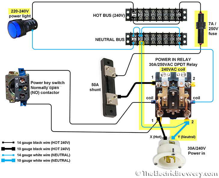
GROUND
There are no changes to the ground wiring as compared to our standard 30A control panel build. If you use a different power in receptacle make sure it has a ground. The ground must be connected to your building's ground plane in the electrical panel using an appropriate power cord.
As mentioned above, countries with 220-240V power will use different 30 amp wall outlets so make sure that the GROUND is connected to the power in connector's G point.
Ground wiring diagram: 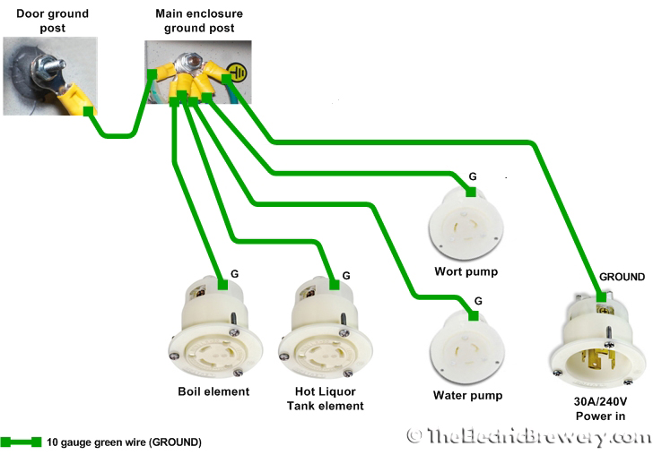
VOLT AND AMP METERS
The doorbell transformers must be changed from 120V to 240V* and the boil relay must use a 240V coil.
Part changes as compared to our standard 30A control panel build:
(Qty: 2) Doorbell transformer (220-240VAC input, 8-24VAC output, any wattage)*
(Qty: 1) 30A/240V DPDT or DPST relay with 220-240V AC coil
*Many doorbell transformers will support both 120V and 240V on the input side. Since these are approximately 10:1 step down transformers, when fed 240V (instead of 120V), the output voltage will be 24V (instead of 12V) which is low enough as the AC to DC power supplies can accept anywhere from 4 to 30V on the input side.
As per the Standard 30A Electric Brewery Control Panel wiring instructions, make sure to adjust the DC power supplies to +5VDC or slightly below before connecting to the meters as otherwise the meters may be damaged.
Volt and amp meter wiring diagram (changes as compared to our standard 30A control panel build are shown in yellow): 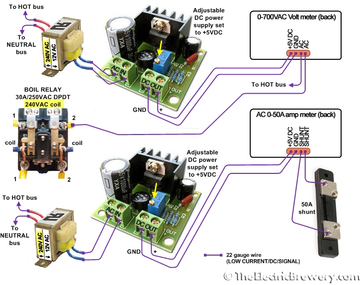
PUMPS
The pump lights must be changed from 120V to 240V. The pumps themselves *must* be 220-240V. 120V pumps will not work.
The pump receptacles on the control panel must be changed from L5-15 (125V) to L6-15 (250V) and the pump plugs must then also be changed to L6-15 to match.
Part changes as compared to our standard 30A control panel build (control panel side):
(Qty: 2) Green 22mm LED pilot light 220-240V AC/DC
(Qty: 2) NEMA L6-15 (250VAC, 15A) twist lock electrical female receptacle
Part changes (pump side):
(Qty: 2) Pump with high temperature stainless steel housing (3/4" NPT male center inlet, 1/2" NPT male outlet, 230VAC)
(Qty: 2) NEMA L6-15 (250VAC, 15A) twist lock electrical male plug
Pump wiring diagram (changes as compared to our standard 30A control panel build are shown in yellow): 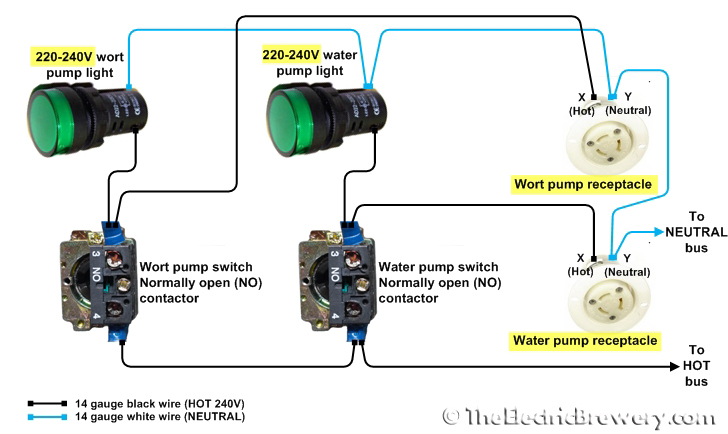
PID CONTROLLERS
There are no changes to the PID wiring as compared to our standard 30A control panel build.
PID controller wiring diagram: 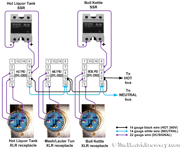
TIMER AND ALARMS
The buzzer and light must be changed from 120V to 240V.
Part changes as compared to our standard 30A control panel build:
(Qty: 1) Buzzer, 22mm, 220-240V AC/DC
(Qty: 1) Red 22mm LED pilot light 220-240V AC/DC
Timer and alarm wiring diagram if using the newer JSL-74A timer (changes as compared to our standard 30A control panel build are shown in yellow): 
Timer and alarm wiring diagram if using the original Eagle B506-5001/Omega PTC-21 timer (changes as compared to our standard 30A control panel build are shown in yellow): 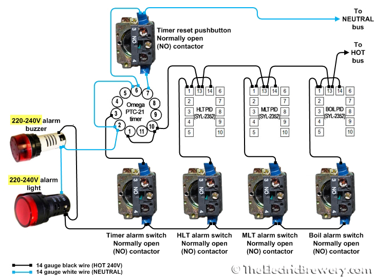
HEATING ELEMENTS
The relays must use 240V coils instead of 120V. Wiring remains the same. We are now supplying power to the elements from the NEUTRAL and HOT lines instead of the two HOT lines. The wire colour is changed in the diagram below to show this. The connection the the second HOT line from the power in receptacle has been removed.
Part changes as compared to our standard 30A control panel build:
(Qty: 1) 30A/240V DPDT or DPST relay with 220-240V AC coil
Heating element wiring diagram (changes as compared to our standard 30A control panel build are shown in yellow): 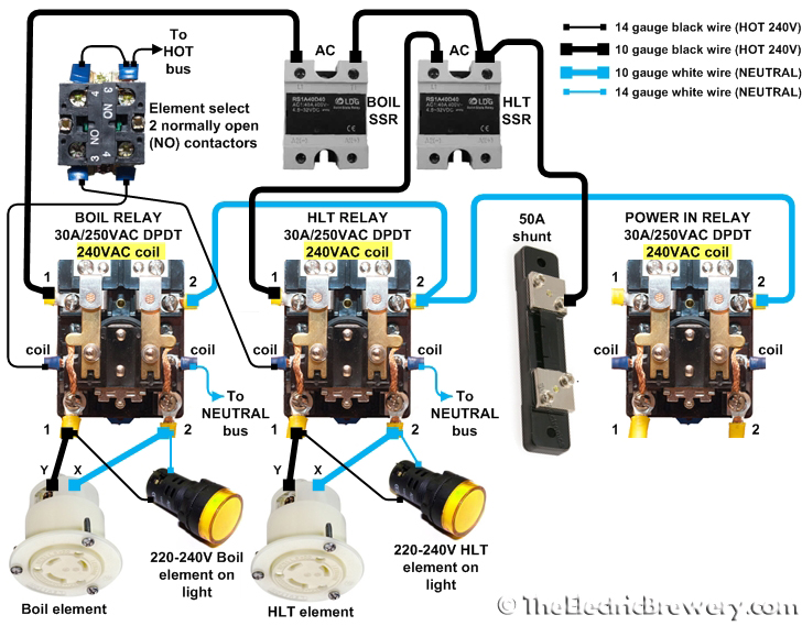
SAFE START INTERLOCK
The relays must use 240V coils instead of 120V.
The POWER KEY switch was previously wired directly to the POWER IN RELAY coil (per the POWER INPUT wiring diagram above). This wire must be removed otherwise the interlock feature will be bypassed and the control panel will power up regardless of how the three other switches are set.
Previously the ELEMENT SELECT switch contained two normally open (NO) contactor that were wired up (per the HEATING ELEMENTS wiring diagram above). We are now adding two normally closed (NC) contactors on top of the existing contactors. Only the new wiring is shown here. The existing wiring does not change.
As per the standard safe start interlock instructions, the two normally closed (NC) contactors that are added to the Element Select switch are screwed on top of the existing normally open (NO) contactors as shown in the picture below. Use two of the unused NC contactors from any of the other switches (other than the pump switches of course). 
Part changes as compared to our standard 30A control panel build:
(Qty: 1) 10A 8-pin 2-pole ice cube plug-in relay with 220-240VAC coil
Safe start interlock wiring diagram (changes as compared to our standard 30A control panel build are shown in yellow): 
Once completed, make sure to follow our control panel setup instructions.
Interested in building your own? Kits are available in our shop.
